Light emitting element drive unit, display module having light emitting element drive unit and electronic apparatus equipped with such display module
a technology of drive unit and drive unit, which is applied in the direction of electroluminescent light sources, static indicating devices, instruments, etc., can solve the problems of large energy loss of constant current drivers and energy loss that reduces the power efficiency of electronic devices such as cellular phones, so as to reduce the energy loss involved and improve the operation efficiency
- Summary
- Abstract
- Description
- Claims
- Application Information
AI Technical Summary
Benefits of technology
Problems solved by technology
Method used
Image
Examples
first embodiment
[0052] Referring to FIG. 1, there is shown an electronic apparatus equipped with a display having a multiplicity of light emitting element groups that are operable at different voltages and driven by a light emitting element drive unit according to the invention. It is noted that the invention can be implemented as a display module equipped with such light emitting element drive unit and such display.
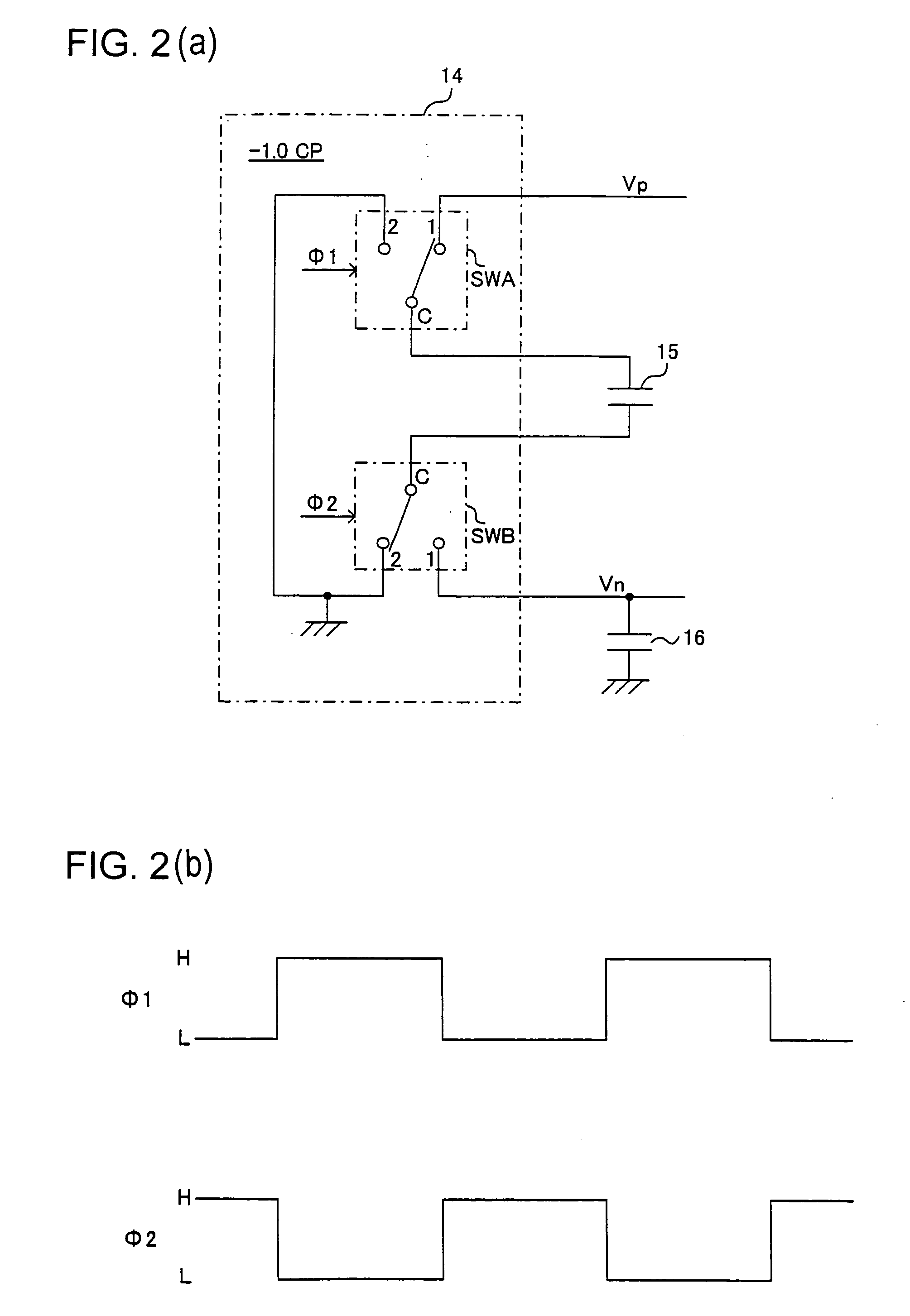
[0053] As shown in FIG. 1, this electronic apparatus has a display 100 and a light emitting element drive unit that comprises a control IC 10 and externally connected IC devices.
[0054] The display 100 is provided with a first light emitting element group 110 that includes two LEDs 111 and 112 connected in series with each other (the group referred to as first LED group), and a second light emitting element group 120 that includes four LEDs 121-124 connected in series in the order mentioned (the group referred to as second LED group). The LEDs 111 and 112 of the first LED group 110 is u...
second embodiment
[0078]FIG. 4 is a circuit diagram of an electronic apparatus equipped with a display having a multiplicity of light emitting element groups in accordance with the invention.
[0079] In the second embodiment shown in FIG. 4, a first driver 17A is connected to the output terminal providing the positive voltage Vp and to one end of the first LED group 110. The other end of the first group 110 is grounded. A second driver 18A is connected to the output terminal providing the positive voltage Vp and to one end of the second LED group 120. The other end of the second group 120 is connected to the output terminal providing the negative voltage Vn. As connected in this way, the first and second drivers 17A and 18A, respectively, have a structure as shown in FIG. 5.
[0080] The constant current driver 17A of FIG. 5 is provided between the output terminal providing the positive voltage Vp and the first LED group 110. The constant current driver 17A has a detection resistor 35 and a P-type MOS tr...
third embodiment
[0083]FIG. 6 is a circuit diagram of an electronic apparatus equipped with a display having a multiplicity of light emitting element (LED) groups in accordance with the invention. In the example shown, the display has a first LED group for emitting red light (R) (referred to as red LEDs), a second LED group for emitting green light (G) (referred to as green LEDs), and a third LED group for emitting blue light (B) (referred to as blue LEDs), three groups being operable at different voltages. Incidentally, the invention may be configured as a display module equipped with the light emitting element drive unit and a display.
[0084] As seen from FIG. 6, this electronic apparatus is equipped with a display 200 and a light emitting element drive unit having a control IC 20 and externally connected ICs.
[0085] The display 200 is provided with a first group 210 of four serially connected red LEDs 211-214, a second group 220 of four serially connected green LEDs 221-224, and a third group 230 ...
PUM
 Abstract
Description
Claims
Application Information
 - R&D
- Intellectual Property
- Life Sciences
- Materials
- Tech Scout
- Unparalleled Data Quality
- Higher Quality Content
- 60% Fewer Hallucinations
Browse by: Latest US Patents, China's latest patents, Technical Efficacy Thesaurus, Application Domain, Technology Topic, Popular Technical Reports.
© 2025 PatSnap. All rights reserved.Legal|Privacy policy|Modern Slavery Act Transparency Statement|Sitemap|About US| Contact US: help@patsnap.com


