Baler

a baler and spherical technology, applied in baling, agriculture tools and machines, agriculture, etc., can solve the problems of high manufacturing and maintenance costs

Inactive Publication Date: 2005-05-05
DEERE & CO
View PDF15 Cites 18 Cited by
  • Summary
  • Abstract
  • Description
  • Claims
  • Application Information

AI Technical Summary

Benefits of technology

[0006] A baler is shown with a baling chamber, a crop material supply unit that can convey crop material into the baling chamber and a device for wrapping a bale with a wrapping web, which has a means that draw off a wrapping web from a supply in the nature of a roll, for instance, the device being able to bring the wrapping web to the crop material supply unit such that it is seized thereby and conveyed in the direction of the bale. In this way, it is possible to forgo supply mechanisms that bring the wrapping web to the bale so that it can be seized by the bale, since this function is already fulfilled in essence by the crop material supply unit. During the actual formation of the bale, the crop material supply unit serves to convey crop material into the baling chamber. During the wrapping process, on the other hand, it conveys the wrapping web in the direction of the bale.
[0008] By virtue of a guide unit, constructed preferably in the manner of a channel and / or a guide surface that extends from the web feed roller up to the crop material supply unit, the supply of the wrapping web to the bale can be further improved, since a contact between the wrapping web and baling material and / or, in particular, moving components of the baler is counteracted. The guide unit can be constructed in the form of a channel that is essentially closed off at least on the top and the bottom, but it can also be a guide surface, preferably provided underneath the wrapping web.
[0011] If the guide unit or the channel or the guide surface interacts with the blower, then the air stream is concentrated by the channel or directed by the guide surface, whereby a targeted guidance of the wrapping web is supported. Additionally, by forming an air cushion on which the wrapping web hovers, the air stream prevents the wrapping web from contacting the channel or a wall of the channel or the guide surface and sticking there. This is particularly favorable if the wrapping web is coated with an adhesive or has adhesive characteristics. It can be provided for the blower to supply the air stream at least over substantially the entire width of the channel by means, for instance, of a supply slit or the like, which yields a uniform distribution. It is also possible for the air introduction to be done over areas or points so as to deliberately advance or lift off the channel certain areas of the wrapping web, which can also be constructed in a special manner for propulsion by an air stream, for instance, by being un-perforated, while the rest of the wrapping web is perforated.
[0012] It can be provided for the wrapping web to detach after termination of the wrapping process, for instance, by having the bale continue to rotate while the feeding of wrapping web from the supply is interrupted. To achieve a uniform detachment edge and thus counteract any tangling of the wrapping web, a cutoff unit can be provided, comprising for instance a blade that cuts or detaches the wrapping web. This cutoff unit can interact with the guide unit in such a manner that the latter serves to back up the wrapping web or hold it in place.
[0017] The guide means can be constructed, for example, as a guide plate on which the wrapping web lies. If the guide means is constructed like a rake, then the wrapping web can lie on the guide means or the tines of the rake, and be brought thereby to the crop material supply unit and removed there from. Dirt and contaminants can fall between the tines of the rake, so that deposits on the guide means are counteracted. Additionally, a rake-like or partially cut-out design of the guide means offers the possibility for the wrapping web to be seized by the crop material supply unit while still lying on the guide means, which favors a good conveyance, particularly at the beginning of the wrapping process.

Problems solved by technology

The problem underlying the invention is seen in the fact that such a baler with a device for wrapping a bale comprises many individual parts for supplying the wrapping web to the bale and is thus expensive to manufacture and maintain.

Method used


Image

  • Baler
  • Baler

Examples


Embodiment Construction

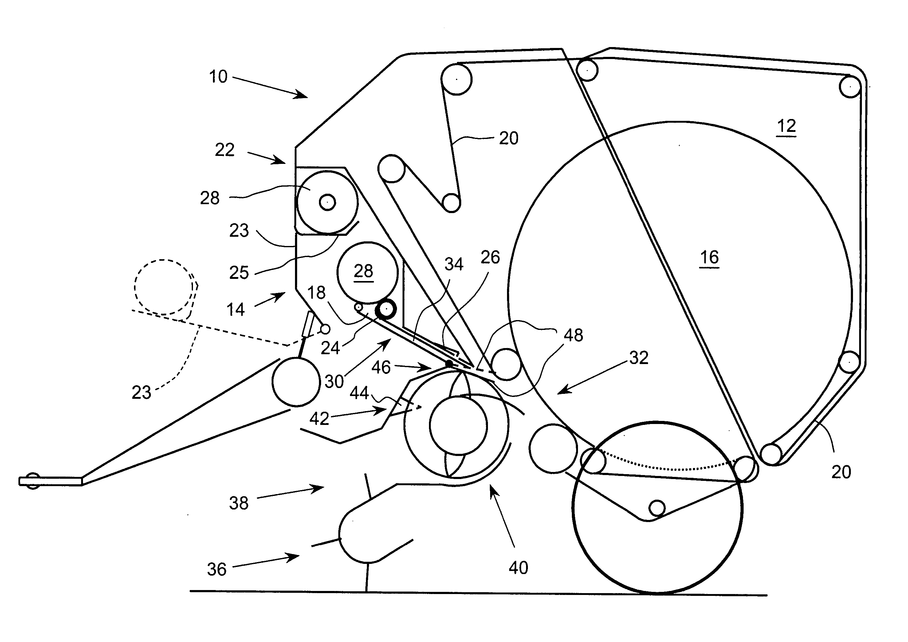
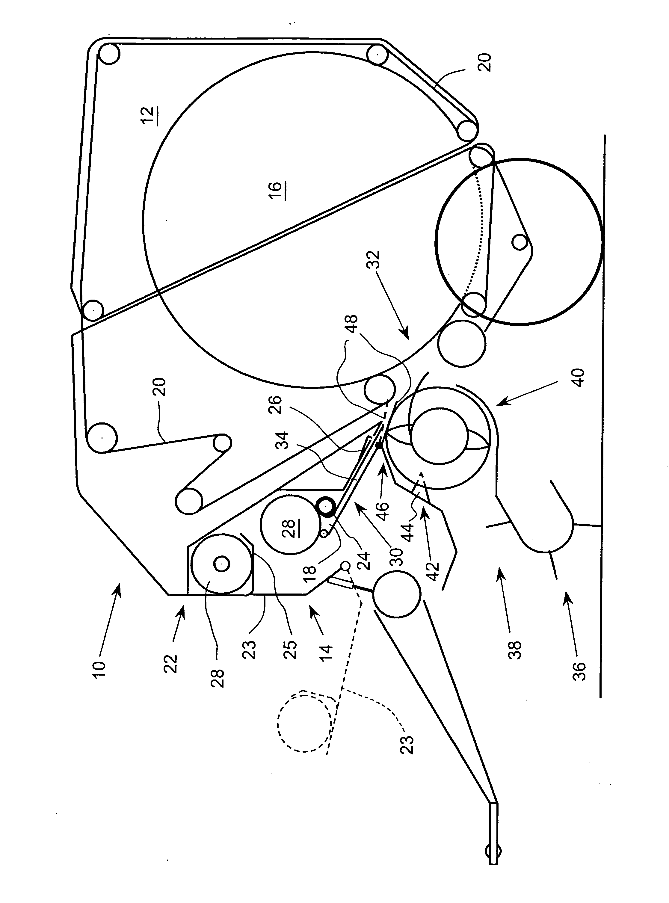
[0024] The sole FIGURE shows a baler 10 of essentially conventional construction with baling chamber 12. Corresponding to the present embodiments, a wrapping material supply arrangement 14 I for wrapping a bale 16 formed in baling chamber 12 with a wrapping web 18 is additionally provided.

[0025] Baler 10 may be of a conventional design, that is, with a baling chamber 12 of constant or variable size that is surrounded by rollers, by chains or by a combination of belts and chains or, as in this embodiment, by belts 20.

[0026] Such a baler 10 can be employed in agriculture for forming bales 16 of crop material, such as straw, hay or grass. Usage in industrial fields is also conceivable, however.

[0027] Wrapping material supply arrangement 14 I is provided in the present embodiment at the front end of baler 10. Wrapping web 18 is supplied through a gap between two adjacent belts 20 to baling chamber 12, where it is entrained by the rotating bale 16. Wrapping material supply arrangement...


PUM


Abstract

A large round baler includes a device for introducing a wrapping web to the baling chamber for wrapping a bale with the wrapping web. During a wrapping procedure, the wrapping web is pulled off a supply roll and directed to a location in front of the baling chamber where it is engaged by a crop supply unit and introduced into the baling chamber where the rotating bale carries the wrapping web about it and becomes wrapped.

Description

FIELD OF THE INVENTION [0001] The invention pertains to a baler with a baling chamber, a crop material supply unit that can convey crop material to the baling chamber, and a device for wrapping a bale with a wrapping web, which has means that pull a wrapping web off a supply in the nature of a roll, for instance. BACKGROUND OF THE INVENTION [0002] DE-C2-36 17 155 shows a round baler with a device for wrapping a bale with a wrapping web and having a feed mechanism that first draws off the wrapping web from a supply in order then to lay it down on a hold-down device and bring it up to a starting roll that seizes the wrapping web and supplies it to the bale to be wrapped. [0003] The problem underlying the invention is seen in the fact that such a baler with a device for wrapping a bale comprises many individual parts for supplying the wrapping web to the bale and is thus expensive to manufacture and maintain. SUMMARY OF THE INVENTION [0004] According to the present invention, there is ...

Claims


Application Information

Patent Timeline
Patent Type & Authority Applications(United States)
IPC IPC(8): A01F15/07
CPCA01F15/0715
Inventor VIAUD, JEANCHAPON, EMMANUEL
Owner DEERE & CO
Why Eureka
Try Eureka