
Method and apparatus for monitoring data storage devices

a data storage device and data technology, applied in the direction of instruments, nuclear elements, nuclear engineering, etc., can solve the problems of data storage devices that will ultimately fail, failure of a particular data storage device, and additional functionality associated with log page data

Inactive Publication Date: 2005-04-28
JONES MICHAEL D
View PDF4 Cites 108 Cited by
  • Summary
  • Abstract
  • Description
  • Claims
  • Application Information

AI Technical Summary

Benefits of technology

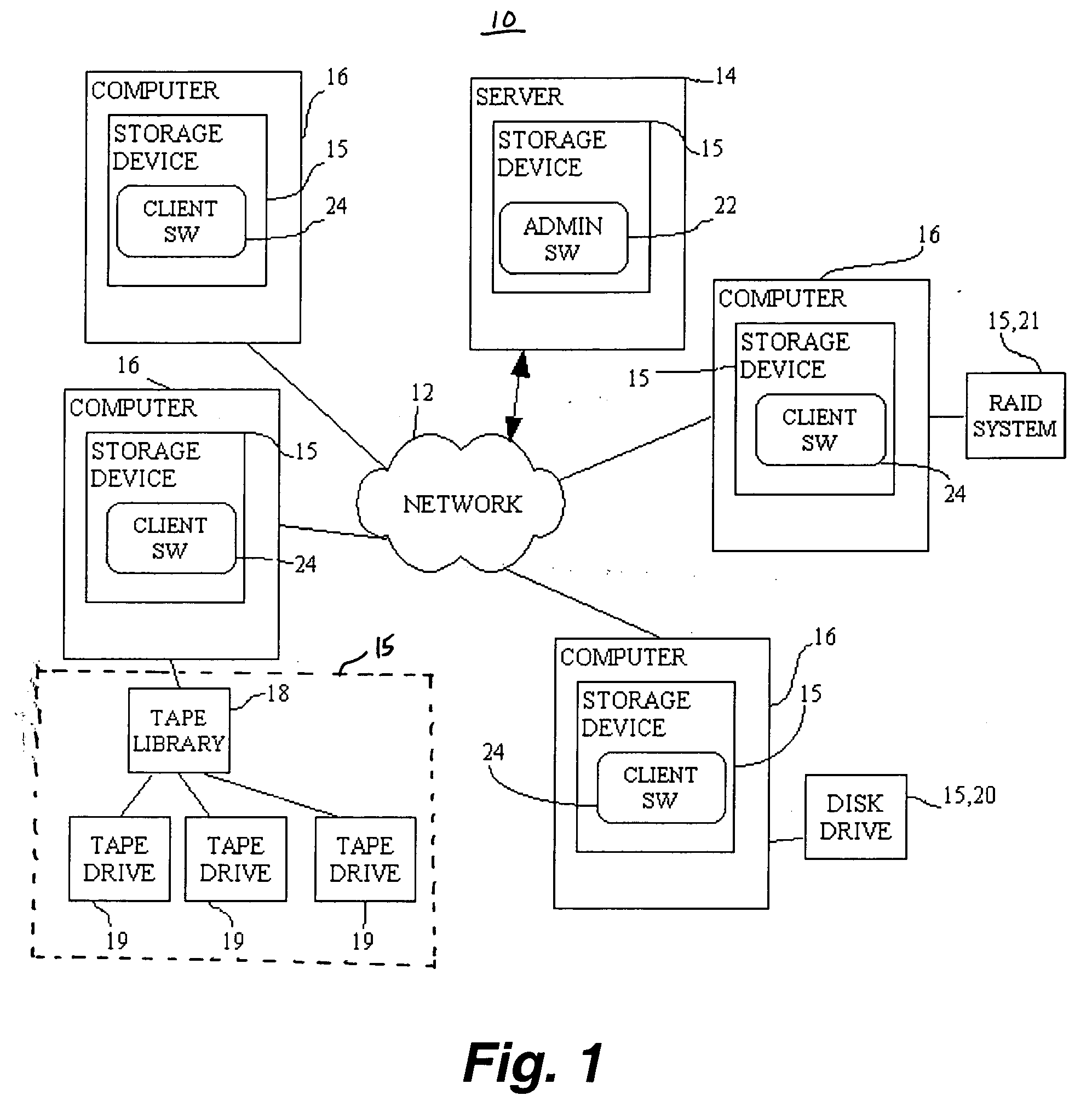
[0008] According to the apparatus / system of the present invention, a computer network is provided having a number of computers which have the ability to communicate with one another through a central server computer, the network corresponding to well-known commercial computer networks which are used within business and government entities. The functionality of the present invention may be achieved through a software application which allows monitoring of each and every data storage device which may exist on the computer network. The software application can be conceptually broken down into an administrator level software application and a server agent level software application. The server agent level includes computer coded instructions / software which is ultimately installed on each computer having its own data storage device(s) in the computer network. The administrator level includes computer coded instructions / software which is installed at a network server computer, or some other designated computer within the network. The administrator software coordinates, organizes, and produces outputs from data gathered from the server agent software installations. The gathered data may be manipulated to provide a user with both realtime and historical information regarding the functioning of each data storage device. The administrator software also provides analytical conclusions directing a user to take appropriate remedial actions, such as to replace a particular storage data device, or take other actions necessary, to prevent loss of data within the computer network.
[0010] Statistical analysis of collected data in the administrator database allows creation of the reports, warning messages, or other outputs which therefore provide early detection of potential failures, or at least of failures which may have just occurred. The present invention also has the capability to track each particular tape or other removable media which is installed on any computer of the network and to notify the system administrator if a faulty tape or other media is later reintroduced for use within a particular computer of the network.

Problems solved by technology

Like any electromechanical device, data storage devices will ultimately fail over a period of time.
However, a user is simply able to view the pre-formatted log page data, and there is no additional functionality associated with the log page data.
Although this log page data may be available, each computer must be checked individually and the ultimate failure of a particular data storage device occurs without any industry standard warning protocols in terms of integrated software within the computers which will automatically alert a user to either impending failure of the data storage device, or possible failure of the device.
As computer networks continue to advance not only in the amount of data which is manipulated across a network, but also in the type of data which is manipulated, the failure of a data storage device can create a catastrophic effect on the overall integrity of a computer network.
Currently, there are no known software applications which monitor much less predict factors in a computer system with regard to data reliability.

Method used


Image

  • Method and apparatus for monitoring data storage devices
  • Method and apparatus for monitoring data storage devices
  • Method and apparatus for monitoring data storage devices

Examples


Embodiment Construction

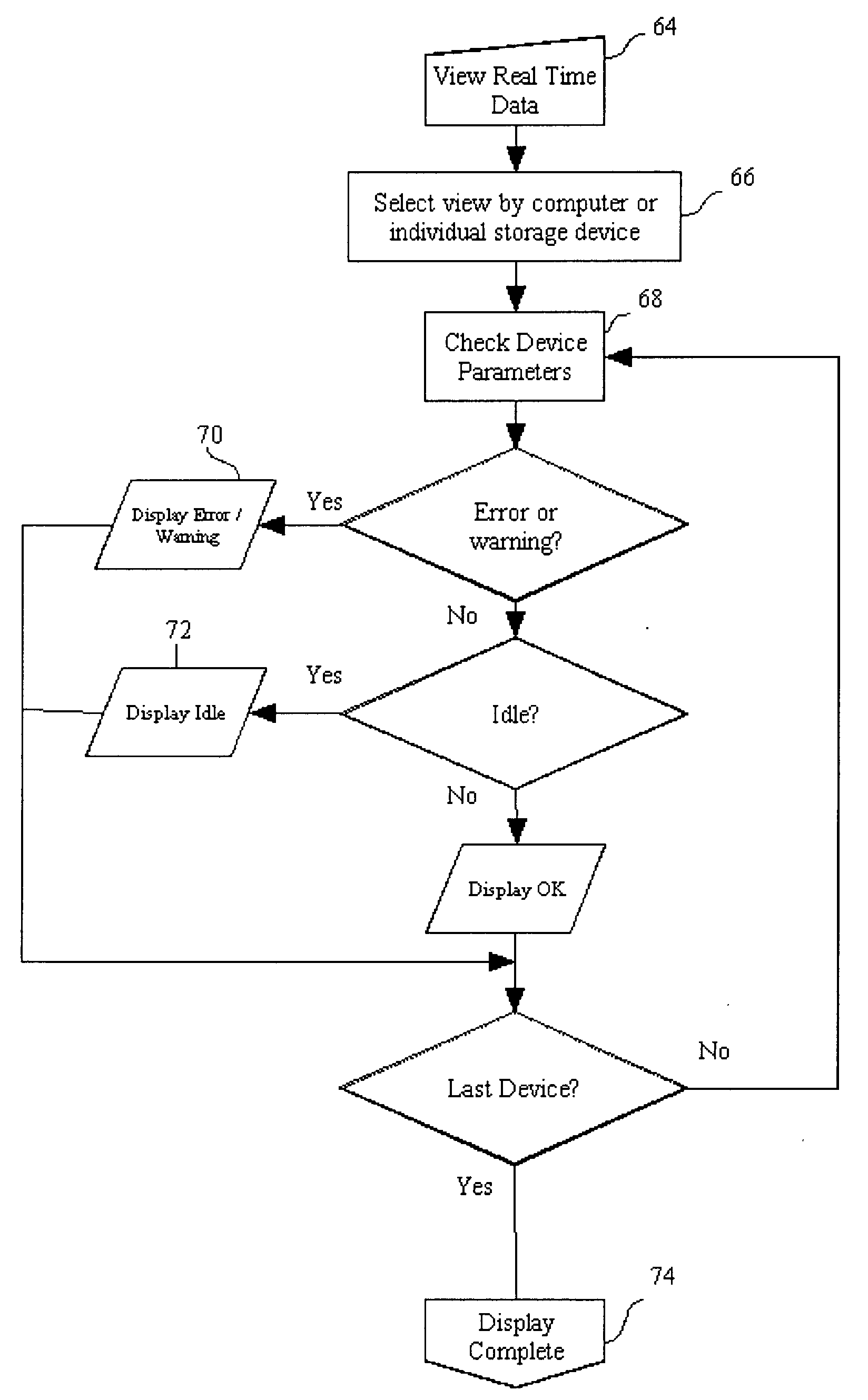
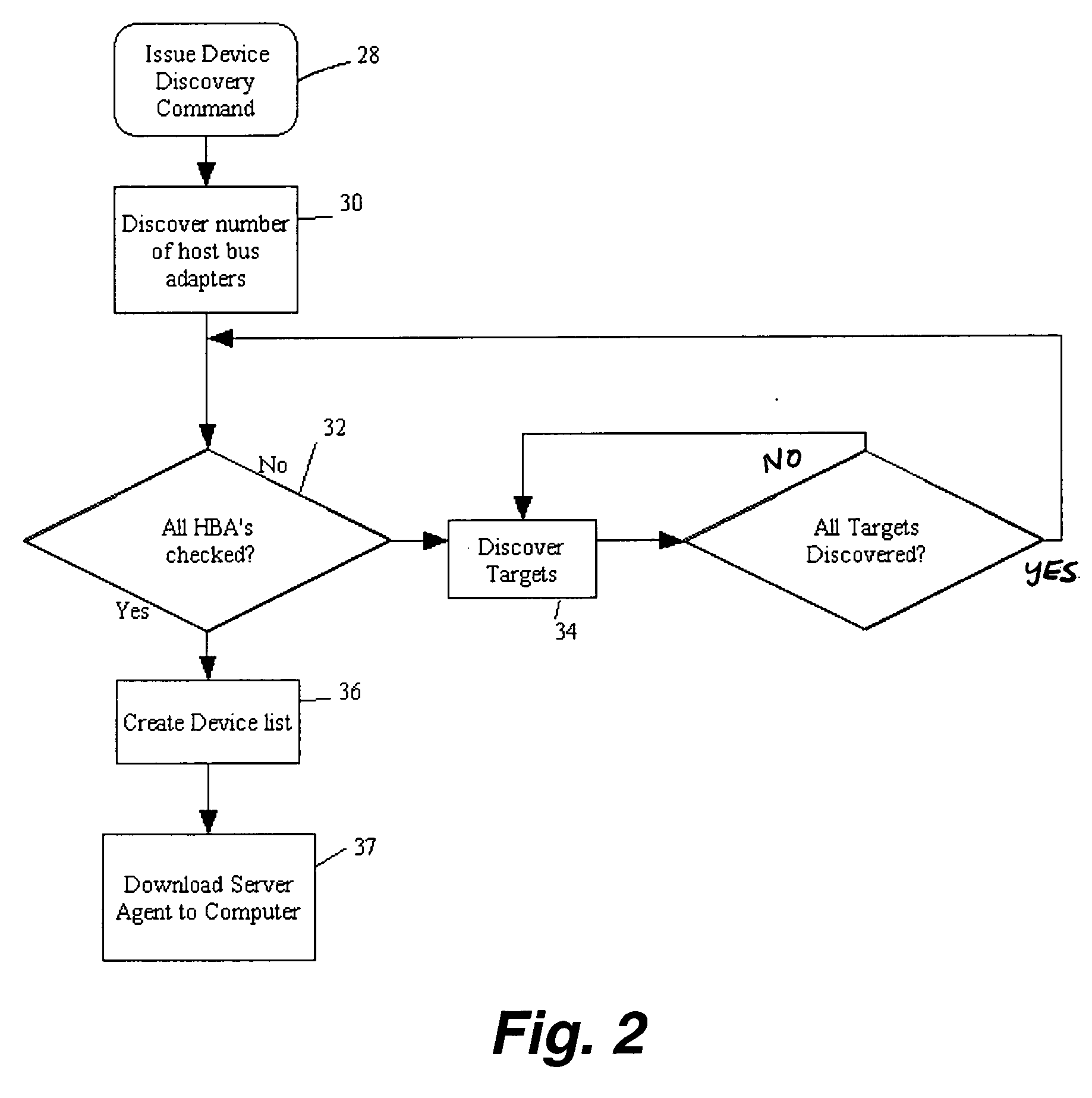
[0031] The apparatus / system 10 of the present invention is depicted within the schematic diagram of FIG. 1. The apparatus / system 10 is incorporated within a computer network 12 which includes a plurality of computers 16 which may be in the form of sufficiently powerful personal computers each having their own central processing unit, main memory, disk storage, tape storage, solid state memory, optical drive or other storage device, as well understood in the art. The computers 16 may have or be associated with one or more storage devices 15. For example, a computer 16 may have or be associated with a monitored storage device 15 comprising one or more tape libraries 18, each tape library including one or more tape drives 19. Alternatively, one or more of the computers 16 may have a monitored storage device 15 comprising a single internal tape drive. Additionally, one or more of the computers 16 may have a monitored storage device 15 comprising a disk drive 20, as illustrated. As a fur...


PUM


Abstract

The monitoring apparatus includes administrator level software installed in one computer of a computer network, and server agent level software installed in other computers of the computer network having corresponding data storage devices. Log page data of monitored data storage devices is retrieved by the server agent level software and then transmitted to the administrator level software. The log page data is stored in a database at the administrator level software and user interface information is generated from the data stored in the database to provide information to a user regarding the status of each monitored data storage device in the computer network. The user interface information may include explanatory text, predictive analysis, and / or graphical information of both realtime and historical performance of the data storage devices. Accordingly, a very large computer network can be monitored at a single location to determine the general status of each data storage device in the network thereby providing early warning of actual or potential failures of the data storage devices.

Description

TECHNICAL FIELD [0001] The present invention relates to a method and apparatus for error monitoring of a data processing system, and more particularly, to a method and apparatus of electronically processing data to monitor and record errors which may occur in data storage devices, and further to provide early warning of a potential future failure of data storage devices on computers across a computer network. BACKGROUND OF THE INVENTION [0002] Data storage devices are integral parts of all computers and data processing systems to include both large and small computer networks. Data storage devices of the most common types include disk drives and tape drives. As well understood by those skilled in the art, both tape and disk drives have the capability to read and write data based upon software which is installed on each computer application and directs such read / write operations. Like any electromechanical device, data storage devices will ultimately fail over a period of time. Accor...

Claims


Application Information

Patent Timeline
IPC IPC(8): G06F11/30G06F15/00G06F15/16G06F15/173G21C17/00H04L69/40
CPCH04L41/06H04L41/147H04L43/045H04L69/329H04L43/0817H04L67/1097H04L69/40H04L43/08H04L41/149
Inventor JONES, MICHAEL D.
Owner JONES MICHAEL D
Learn More