
Shock protection apparatus for hard disk drive

a technology for hard disk drives and shock protection apparatuses, which is applied in the direction of recording information storage, recording carrier contruction details, instruments, etc., can solve the problems of physical damage to the recording surface or the head, the entire recording surface of the disk may become unusable, and the inability to store/reproduce data located in at least a damaged part of the disk, etc., to achieve the effect of reducing the influence of the change over time of the shock-cushioning material

Active Publication Date: 2005-04-28
PANASONIC CORP
View PDF3 Cites 29 Cited by
  • Summary
  • Abstract
  • Description
  • Claims
  • Application Information

AI Technical Summary

Benefits of technology

[0025] Therefore, an object of the present invention is to provide a shock protection apparatus for a hard disk, which employs a combination of a shock-cushioning structure using a shock-cushioning material and an emergency retracting mechanism which operates based on detections of head-slap signs. I

Problems solved by technology

During the operation of a HDD, if a violent impact force in the vertical direction is applied to the recording surface of a disk, in particular, there is a high possibility of causing a phenomenon known as a “head slap” where the head slider hits the disk surface due to the head slider being displaced by a distance greater than the flying height.
The head slap may cause physical damage to the recording surface of the disk or to the head, whereby it becomes impossible to store / reproduce data located in at least a damaged part of the disk.
In the worst case, the entire recording surface of the disk may become unusable, i.e., the HDD may get damaged.
During carriage or moving, the user may accidentally bump or drop the notebook PC against or onto a hard surface.
Since notebook PCs, etc., are designed to be compact and light-weight so as to ensure portability, such an impact force may be easily transmitted to the HDD incorporated in the computer, thereby damaging the HDD.
Since the head is in a head load state not only during an access operation to the disk (i.e., the HDD is in an operating state) but also immediately after the access operation (i.e., the HDD is in a non-operating state), if a violent impact force in the vertical direction is applied to the HDD immediately after the access operation, a head slap may occur, thereby damaging the head or the disk.
That is, when the HDD is in a head unload state and at the time of changing its operation mode, the HDD cannot appropriately handle abrupt, violent impact forces.
However, since the shock resistance specification during the operation is 200 G, the shock resistance falls short by as much as 300 G, with respect to an impact force of 500 G. Therefore, if an impact force of 500 G is applied to the HDD 1 during the operation, i.e., in a head load state, physical damage may occur due to a head slap phenomenon.
That is, with this cushioning structure, the HDD 1 installed on the notebook PC cannot be protected from shocks resulting from drops of 90 cm, during the operation.
However, it is very difficult to design a shock-cushioning structure which satisfies both operating and non-operating conditions.
This leaves concerns about deterioration in elasticity of the shock-cushioning material resulting from change over time.
In addition, the change over time causes a decrease in the volume of the shock-cushioning material.
That is, as a result of deterioration of elasticity and a decrease in volume, the shock-cushioning material would lose its originally-set desired cushioning effect.
However, the use of extra amount of a shock-cushioning material to compensate the change over time may become a great impediment to designing of a compact, light-weighted notebook PC whose portability is very important.
The first problem is the necessity of estimating in advance a reduction in cushioning performance of a shock-cushioning material resulting from the change over time and adding a sufficient volume of the shock-cushioning material to compensate the estimated reduction in cushioning performance.
To do so, the device having the HDD installed thereon needs a space therein for enclosing the added cushioning material, which hinders obtaining a compact and light-weighted device.
The second problem is that materials capable of providing a shock-cushioning effect which satisfies required specification values for both operating and non-operating conditions do not exist or are not yet in actual use, and thus are not available.
This necessitates the use of a plurality of materials with different elastic moduli which are separately designed for operating and non-operating states, making the structure of a shock-cushioning structure complicated.
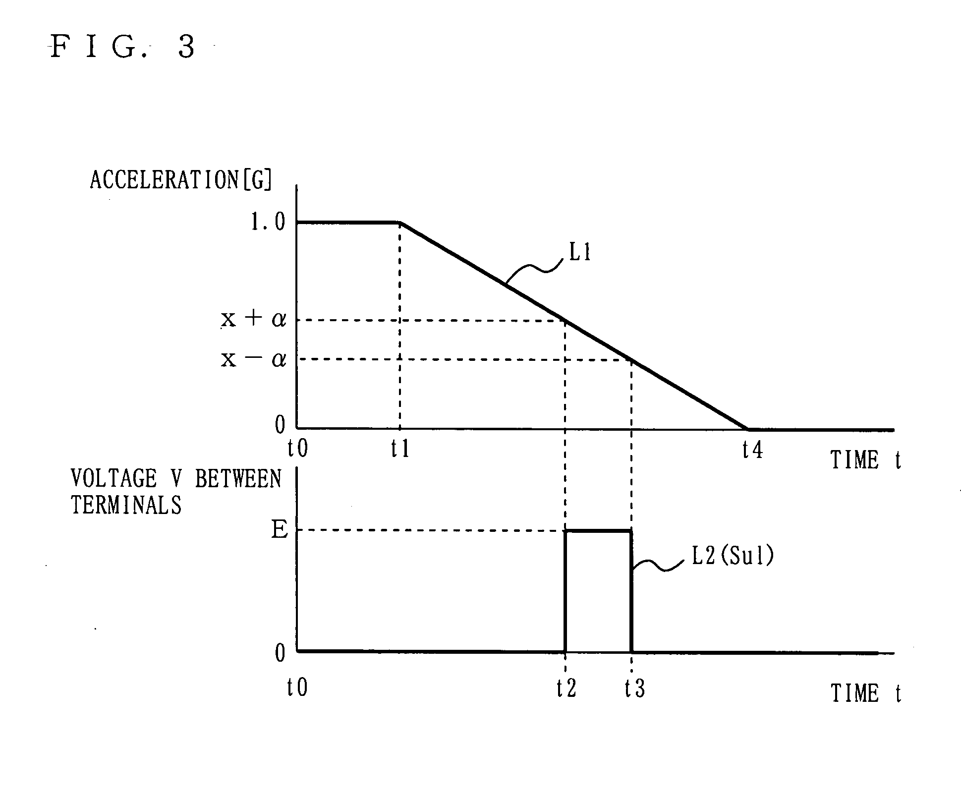
However, in practice, the acceleration applied to the HDD during free fall changes from 1 G to 0 G. Thus, it is nearly impossible for the acceleration sensor to detect such a small rate of change in acceleration.
However, if the threshold value for determination is too low, even vibrations generated by the HDD itself or transmitted externally may also be falsely detected as a drop of the HDD.
Any of the head retracting mechanism which operates based on the operation mode of the HDD, the head retracting mechanism which operates based on the change in acceleration of the HDD, and the shock-cushioning structure using a shock-cushioning material discussed above have problems in being used to protect the HDD installed on a portable device, such as a notebook PC or information terminal, from shocks.
Further, it is very difficult to construct a shock-cushioning structure using a plurality of shock-cushioning materials, which can absorb the difference of 600 G. Even if it is constructed, such a shock-cushioning structure is complicated and large in size and weight, and thus cannot be used in a portable device whose being compact and light-weight are important, as is the HDD to be protected.
In addition, a problem resulting from degradation of the shock-cushioning properties of a shock-cushioning material due to the change over time cannot be solved, either.
Further, it is obviously impossible to solve a problem resulting from the fact that the acceleration sensor cannot promptly and properly detect a head-slap sign of the HDD.

Method used


Image

  • Shock protection apparatus for hard disk drive
  • Shock protection apparatus for hard disk drive
  • Shock protection apparatus for hard disk drive

Examples


Embodiment Construction

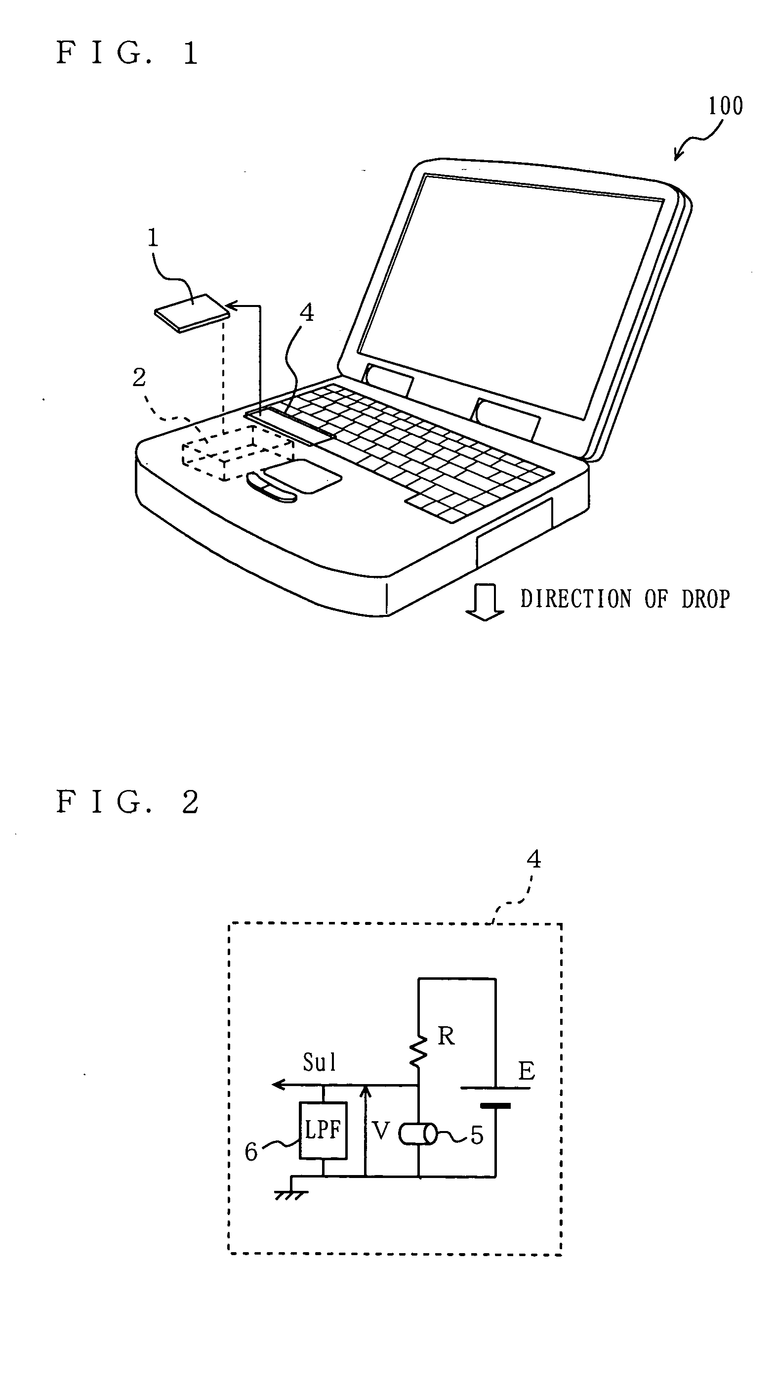
[0034]FIG. 1 shows an example case where a shock protection apparatus for a hard disk drive, according to the present invention is incorporated in a notebook PC. A HDD 1 is enveloped by a shock-cushioning material 3 (not shown) and mounted in a HDD pack 2. The HDD pack 2 and a head-slap sign detector 4 are installed on a notebook PC 100. The shock-cushioning material 3 has characteristics such as low stiffness and low resilience. The shock-cushioning material 3 holds the HDD 1 so as to be enveloped thereby and installed in the HDD pack 2, and protects the HDD 1 from shocks.

[0035] As shown in FIG. 2, the head-slap sign detector 4 generates an emergency unload signal Sul by means of a zero-gravity sensor 5 and outputs the signal Sul to the HDD1. A low-pass filter (LPF) 6 is provided to prevent chattering caused by the zero-gravity sensor 5 intermittently sensing a pseudo acceleration, which is similar to that generated at the time of a drop, generated when vibration is applied to the...


PUM


Abstract

A shock protection apparatus includes a zero-gravity sensor 5 for detecting whether a hard disk drive 1 is in a zero-gravity state and accordingly generating a zero-gravity detection signal Sul; and ahead-slap sign detector 4 for outputting to the hard disk drive a signal Sul for retracting a head, if the hard disk drive 1 is determined to be in a zero-gravity state as detected by the zero-gravity detection signal Sul. In the shock protection apparatus, the influence of change over time of a shock-cushioning material is reduced, the difference in shock-resistant performance between operating and non-operating states is reduced, and signs of a head slap are detected promptly and properly to urgently retract the head.

Description

BACKGROUND OF THE INVENTION [0001] 1. Field of the Invention [0002] The present invention relates to a shock protection apparatus for a hard disk drive, and more particularly to a shock-cushioning apparatus for protecting a hard disk installed on a device from shocks as a result of the device being dropped. [0003] 2. Description of the Background Art [0004] A hard disk drive (hereinafter referred to as a “HDD”) is a device that stores or reproduces data in a desired storage location by moving its magnetic head to the desired location in a head load state where a predetermined amount of clearance is maintained between the head and the surface a disk rotating at high speed. To increase the recording density of HDDs, the flying height between the disk surface and the head slider surface is getting smaller year by year. [0005] During the operation of a HDD, if a violent impact force in the vertical direction is applied to the recording surface of a disk, in particular, there is a high p...

Claims


Application Information

Patent Timeline
IPC IPC(8): G11B5/54G11B33/14G11B19/04G11B21/02G11B21/12G11B33/08
CPCG11B5/54G11B33/08G11B21/12G11B19/043
Inventor YOSHIDA, TOYOSHI
Owner PANASONIC CORP
Learn More