Optical apparatus with loss compensation capability and optical amplifier for loss compensation
a technology of optical amplifier and optical apparatus, applied in the direction of semiconductor amplifier structure, electromagnetic transmission, semiconductor laser, etc., can solve the problems of large coupling loss of fiber with fiber than a fiber type device, high spatial coupling precision, and inability to integrate, so as to reduce the noise characteristic of optical amplifier and reduce the cost. , the effect of reducing the noise characteristic of the optical amplifier
- Summary
- Abstract
- Description
- Claims
- Application Information
AI Technical Summary
Benefits of technology
Problems solved by technology
Method used
Image
Examples
first embodiment
[0091]FIG. 2 shows a configuration of the optical apparatus having the loss compensation capability according to the present invention.
[0092] In FIG. 2, the optical apparatus comprises, for example, an input side optical parts 2, an amplification medium 3, a loss medium 4, and an output side optical parts 5 between an input connector 1A as an input terminal and an output connector 1B as an output terminal, and a control circuit 6 as a gain control unit for controlling the gain in the amplification medium 3.
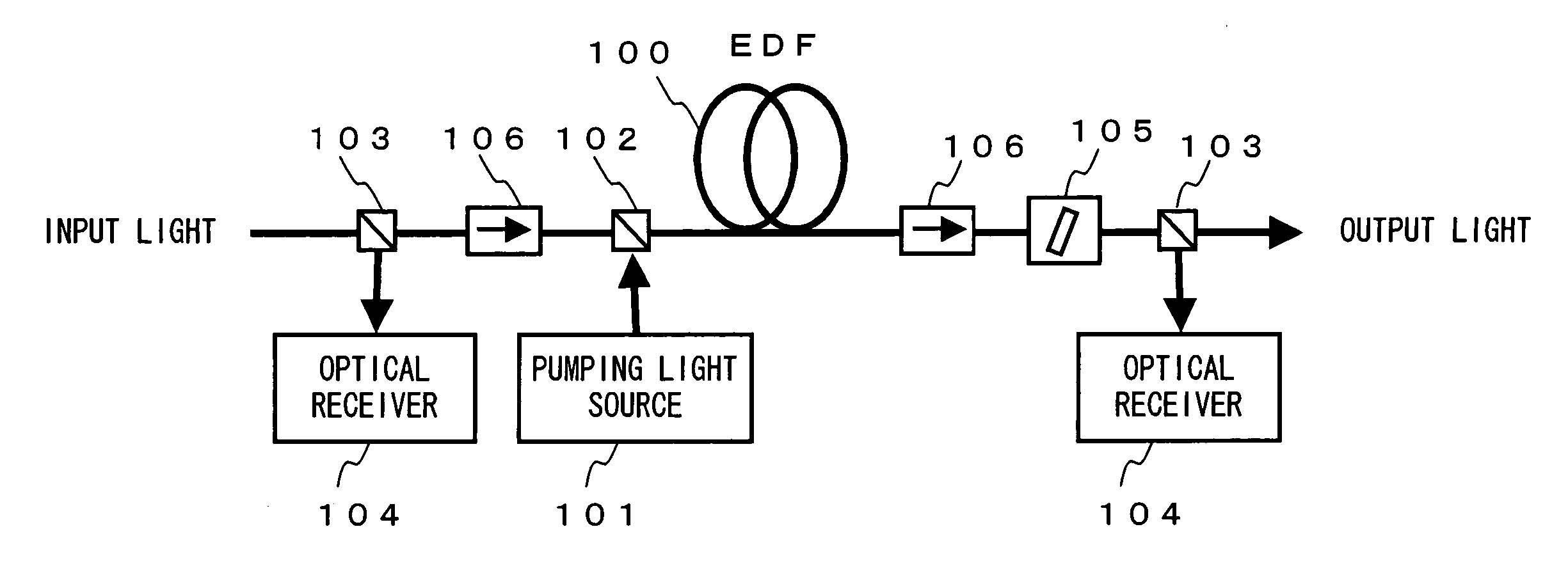
[0093] The input side optical parts 2 comprises, for example, an input connector 1A; a branch unit 2A and a monitor 2B as an input side monitor unit for monitoring the power of the light input through the input connector 1A and transmitted to the amplification medium 3; and a pumping light source 2C and a wavelength multiplexer 2D for providing pumping light for the amplification medium 3. The branch unit 2A branches a part of the input light provided for the input connector 1A a...
second embodiment
[0126] Described below is the optical apparatus having the loss compensation capability according to the present invention.
[0127]FIG. 13 shows the configuration of the second embodiment of the optical apparatus. The components similar to those according to the first embodiment are assigned the same reference numerals, and the explanation is omitted here, which also holds with other embodiments.
[0128] In FIG. 13, In the configuration of the optical apparatus according to the present embodiment, the portions different from those in the configuration of the first embodiment shown in FIG. 2 are represented by an input side optical parts 2′ for the input side optical parts 2. The input side optical parts 2′ is different from the input side optical parts 2 in that an isolator 2E is connected to the optical path between the branch unit 2A and the wavelength multiplexer 2D. The other components in the configuration are the same as those according to the first embodiment.
[0129] The isolato...
third embodiment
[0153] Described below is the optical apparatus having the loss compensation capability according to the present invention.
[0154]FIG. 23 shows an example of the outline of the configuration of the optical apparatus according to the third embodiment.
[0155] In FIG. 23, the optical apparatus according to the present embodiment can be further downsized and cost-reduced for an optical amplifier for loss compensation by incorporating a plurality of optical apparatuses according to the first embodiment into one system.
[0156] In this example, three optical amplifiers for loss compensation for three loss media 4A, 4B, and 4C are arrayed for each component, and the components capable of being collectively integrated are incorporated into an array structure.
[0157] The technology of collectively integrating various optical parts configuring each optical apparatus can be, for example, the optical waveguide technology, the integration through spatial coupling, the fiber array method, the fiber...
PUM
 Abstract
Description
Claims
Application Information
 - R&D
- Intellectual Property
- Life Sciences
- Materials
- Tech Scout
- Unparalleled Data Quality
- Higher Quality Content
- 60% Fewer Hallucinations
Browse by: Latest US Patents, China's latest patents, Technical Efficacy Thesaurus, Application Domain, Technology Topic, Popular Technical Reports.
© 2025 PatSnap. All rights reserved.Legal|Privacy policy|Modern Slavery Act Transparency Statement|Sitemap|About US| Contact US: help@patsnap.com


