[0019] It is apparent that all these dressing aids are separate devices from the tubular garment or covering. The purpose of this invention is to avoid having to use a device separate from the sock or
condom to assist in the donning of the said tubular devices.
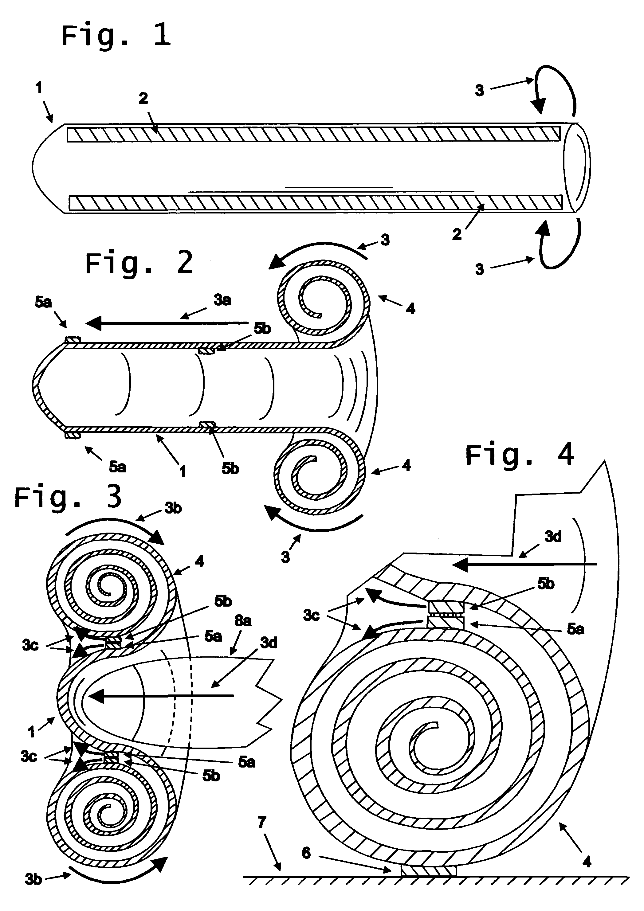
[0023] It is important to note that the springy elements act in a direction that is parallel to the longitudinal axis of the tubular element 1. This means that they can be used in combination with elastic socks, such as those used to prevent
Deep Vein Thrombosis (DVT), that have elasticity principally in a direction at right angles to the longitudinal axis of the tubular element 1. This makes this invention applicable to the very type of sock that is so difficult to put on and off.
[0024] These springy elements can be attached to the exterior and or interior of the said tubular elements by various means well known to the art. This would include adhesives, or flexible pockets, similar to those that accommodate battens in sails. These pockets can be formed by attaching various
layers of a multi-layered tubular element, or by separate flexible strips attached to the said tubular element. The means for attachment of the said
layers or pockets can be effected by means well known to the art, which would include stitching, adhesives, cross-linking polymers by chemical or thermal means to name a few examples. The springy elements themselves can be made of any springy material, such as steel, or plastic. Some preferred embodiments use only enclosed elongated pockets or ribs formed or molded in the material from which the tubular element is made, or attached to it, or a combination of the two, and containing air or some other suitable gas that can be at
ambient pressure or some other pressure and that becomes or is further compressed in the loaded state and expands as it unloads and springs back. These
balloon type springy elements are most suitable for condoms, but can of course be used for other tubular garments or covering elements. In a
condom, these elongated pockets or rigs can be formed from the proximal end of the tubular element by adding fingers to the mold along side the tubular dip mold. These fingers will form pockets in the wall of the
condom, with open proximal ends which, after inflating the pockets, can be then sealed by various methods well known to the art. The springy elements in the condoms can be located where they will have the least effect on sensitivity and can be straight or curved to enhance the sensory experience.
[0026] Some preferred embodiments include springy elements that are made of
Shape Memory Alloy (SMA) or other memory materials that exhibit shape
recovery. These springy elements can be attached to or form a part of the tubular element or both. These materials have the
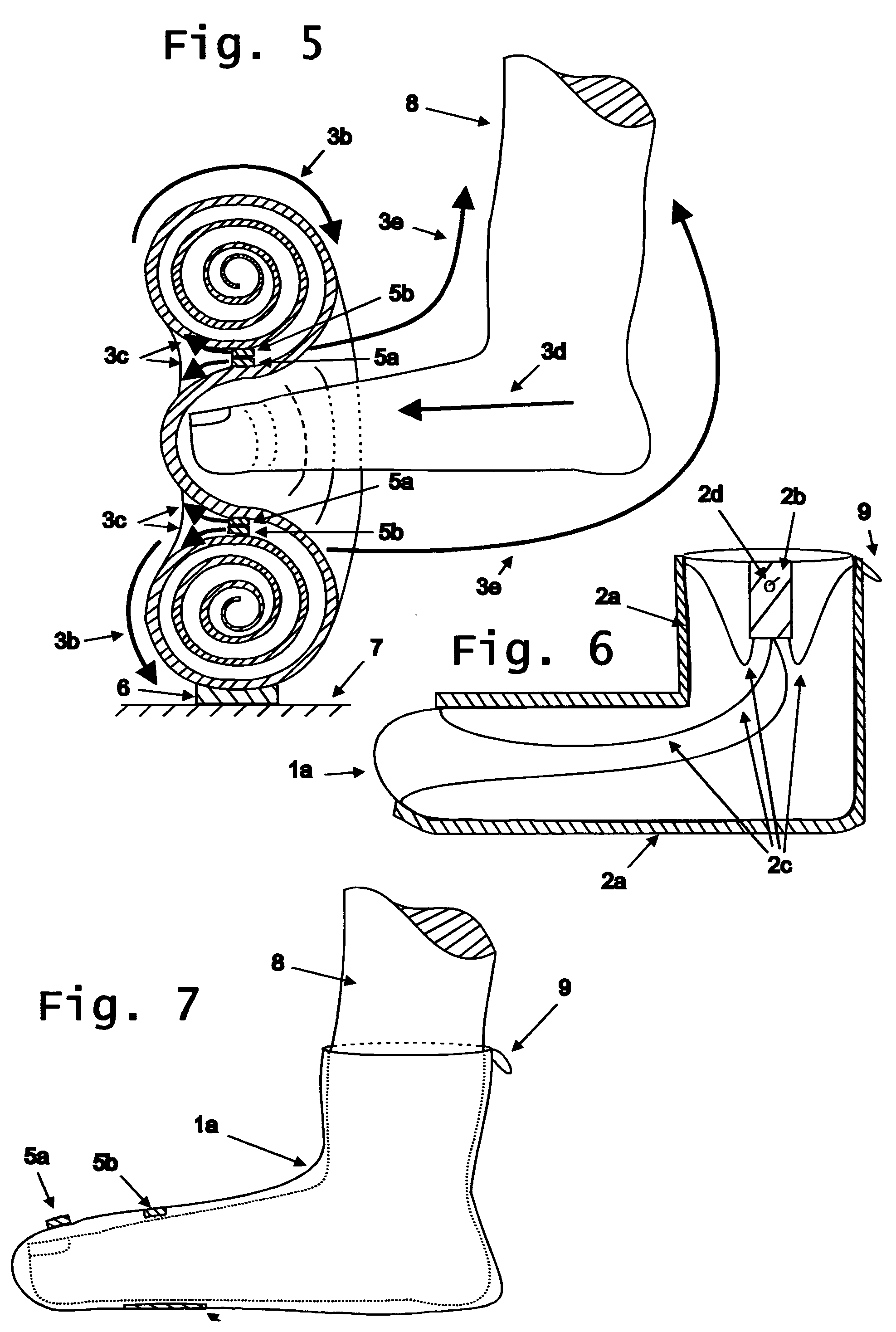
advantage of unloading, or recovering a memorized shape, in response to temperature change, which can be supplied by the heat of the foot, or heat applied by separate means such as a bath, a hair dryer or be effected by resistive electrical heating of the SMA springy element, which exhibits good resistive electrical properties. For example, using these materials the tubular element can be rolled-up to load the “springy element” while in the martensitic state, which is relatively unspringy or floppy. It can then be unloaded by heating it above the Austenitic start temperature and to fully unload them at the austenitic finish temperature. This unloading causes the SMA or other similar material to recover the shape that has been previously imparted into it, usually at very high temperature, which in this case would be approximately straight, with perhaps a slight curve for the heal. This recovered shape acts to unroll the rolled sock over the wear's foot and thus put itself on the wearer's foot. The heating necessary to cause this
martensite to
austenite transformation and thus the
recovery of the imparted shape, can be supplied by the elevated temperature of the wearer's foot, or by some external temperature source, such as a hair blower or by electrically heating (resistive) the SMA material that comprises the springy element. Once the sock is on the wearer's foot, the springy element can return by cooling to it martensitic form and the sock will remain on the wear's foot. Removal of the sock can be then effected by normal means, assisted by a hook or loop attached to the top or near the top of the sock
cuff.
[0030] Some preferred embodiments include a ring that holds-open the tubular element at a minimum
diameter so the wearer can place the distal end of the foot, hand or other body part into the orifice of the tubular element, while it is rolled-up into its approximate torus shape; but allow for radial enlargement of the tubular element to accommodate larger parts of the body, over which the rolled-up tubular element unrolls. In those cases where the tubular element is radially elastic, this ring also allows the tubular element to assume a
diameter less than the said minimum ring
diameter when that part of the tubular element has been rolled-off of the ring. In the case of
elastic stockings, or other elastic coverings, the ring also reduces the collective inward
radial compression of the sock or other covering against the body part where the sock is rolled-up, when it is rolled-on to the body part, making the donning more comfortable.


