Image forming apparatus

a technology of forming apparatus and forming chamber, which is applied in the direction of electrographic process apparatus, instruments, corona discharge, etc., can solve the problems of non-image parts, unable to obtain clear color images, and unable to uniformly charge toner, so as to improve the transfer efficiency, reduce the amount of fog, and improve the effect of transfer efficiency

Inactive Publication Date: 2005-04-21
SEIKO EPSON CORP
View PDF8 Cites 1 Cited by
  • Summary
  • Abstract
  • Description
  • Claims
  • Application Information

AI Technical Summary

Benefits of technology

[0027] In an image forming apparatus for developing a latent image on a latent image carrier with a negatively charged toner, the present invention can reduce the amount of fog on non-image portion with toner particles on the photoreceptor during development and can improve the transfer efficiency. According to the present invention, positively charged toner particles adhering to the latent image carrier can be converted into negatively charged toner particles because of the contact with the intermediate transfer medium, thereby improving the transfer efficiency from the latent image carrier to the intermediate transfer medium. According to the present invention, since toner particles can be converted into negatively charged toner particles at contact between the toner and the latent image carrier and at contact between the toner on the latent image carrier and the image transfer medium, negative charging can be conducted even when negative charging is insufficient, thereby further improving the transfer efficiency.
[0028] Since the amount of fog toner on non-image portions with toner particles on the photoreceptor during development can be reduced and the transfer efficiency can be improved, thereby reducing the consumption of the toner. Since the cleaning toner amount is reduced, reduction in running cost and reduction in size of the cleaning toner container can be achieved.

Problems solved by technology

However the magnetic single-component toner has such a problem that clear color images are not obtained due to the opacity of magnetic material thereof.
For obtaining high-quality record images with the non-magnetic single-component toner, there is a problem how to uniformly charge the toner particles
Even when the relation of the work functions of the aforementioned three components is satisfied as disclosed in the publication, there are problems that a phenomenon called “fog”, in which non-image portions are developed, may still occur because toner particles have a particle size distribution and that it is impossible to increase the transfer efficiency.
However, the use of such a toner reduces the fluidity of toner due to the small particle size so that it is hard to cause triboelectric charging relative to a development roller or a toner layer thickness regulating member.
As a result, it is impossible to give sufficient charge.
In case of toner for negative charge, there is a problem that some toner particles may be positively charged due to inductive charge.
Particularly, in an image forming apparatus which forms images by negative charge reversal developing, there is a problem of the toner and a photoreceptor that positively charged toner particles on non-image portions of a latent image carrier (photoreceptor) make “fog”, thus increasing the actual consumption of toner and also increasing the cleaning load of the photoreceptor.
If a large amount of superplasticizing agent is added as an external additive to the toner in order to resolve the aforementioned problem, there may be another problem of reducing the fixing property.
In a color image forming apparatus using an intermediate transfer medium, there is a problem that positively charged toner particles on a photoreceptor, if any, reduce the transfer efficiency to the intermediate transfer medium.

Method used


Image

  • Image forming apparatus
  • Image forming apparatus
  • Image forming apparatus

Examples


example 1

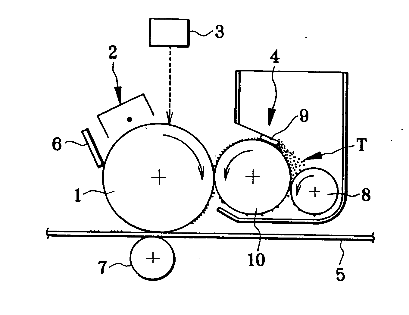
[0202] The toner (1), the toner (4), and the organic photoreceptors [OPC (1), OPC (4), OPC (5)] obtained above were employed to have combinations as shown in Table 1 and adopted to the apparatus of contact single-component developing method shown in FIG. 1.

[0203] For tests, the peripheral velocity of the organic photoreceptor was set to 180 mm / s. The development roller (1) obtained above was employed and the peripheral velocity thereof was set to have a specific ratio of 2 relative to the organic photoreceptor. The development roller was pressed against the organic photoreceptor at pressing load 40 gf / cm with a nip width of 1.5 mm.

[0204] A toner regulating blade was made by bending the end of a SUS plate of 80 μm in thickness by 10° to have projection length of 0.6 mm. The work function was 5.01 eV. The toner regulating blade was arranged to be pressed against the development roller with a linear load of 33 gf / cm in such a manner as to make the toner layer on the development rolle...

example 2

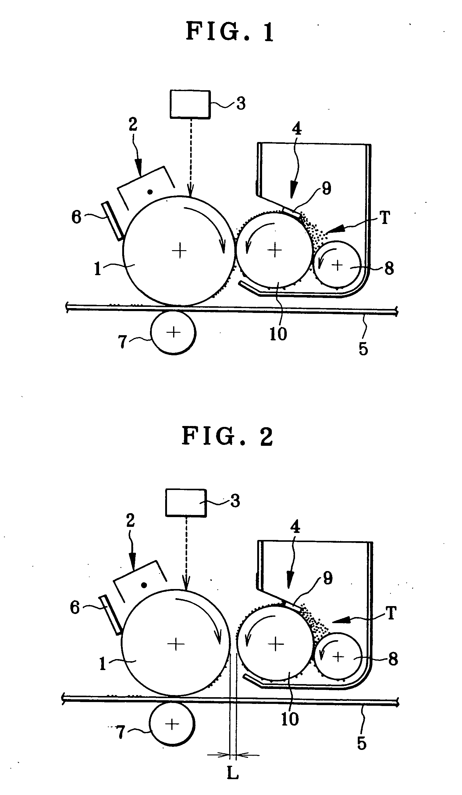
[0215] The toner (1), the toner (4), and the organic photoreceptors [OPC (1), OPC (4), OPC (5)] obtained above were employed to have combinations as shown in Table 2 and adopted to the apparatus of non-contact single-component developing method shown in FIG. 2.

[0216] For tests, the peripheral velocity of the organic photoreceptor was set to 180 mm / s. The development roller (1) was employed and the peripheral velocity thereof was set to have a specific ratio of 2 relative to the organic photoreceptor. A development gap L was set to 210 μm (the space was adjusted by a gap roller). A developing bias was applied under condition that an alternating current (AC) to be superimposed on a direct current (DC) of −200 V was set to have a frequency of 2.5 kHz, and P-P voltage was set to 1500 V.

[0217] Similarly to Example 1, a regulating blade- made of a SUS plate of 80 μm in thickness was used as the toner regulating blade. The toner regulating blade was arranged to be pressed against the dev...

example 3

[0222] The toners for four colors: the cyan toner (1); the magenta toner (4); the yellow toner (5); and the black toner (6), and the organic photoreceptor [OPC (4)] obtained above were combined to form full-color images. As an image forming apparatus, a four-cycle color printer of the non-contact developing type as shown in FIG. 3 (in this case, however, the aluminium pipe of the organic photoreceptor [OPC (4)] was 85.5 mm in diameter) was assembled. In addition, a tandem color printer of the contact developing type as shown in FIG. 4 (in this case, however, the aluminium pipe of the organic photoreceptor [OPC (4)] was 40 mm in diameter) was assembled.

[0223] Either printer can provide uniform fullcolor images. After character image corresponding to color original containing 5% each color was continuously printed on 10000 sheets of paper, the total amount of four color toners collected by cleaning the photoreceptor was measured. In case of the four cycle type color printer shown in ...


PUM


Abstract

An image forming apparatus of the present invention comprises: a latent image carrier; and a developing means for charging a toner into a negative polarity by triboelectric charging, for converting an electrostatic latent image on said latent image carrier to a visible image with said toner and is characterized in that (1) the work function (Φt) of said toner is set to be larger than the work function (ΦOPC) of the surface of said latent image carrier, or (2) in case that the apparatus is of a type transferring the visible image to an intermediate transfer medium, the apparatus is characterized in that the work function (Φt) of said toner is set to be larger than the work function (ΦTM) of the surface of said intermediate transfer medium or (3) the work function (ΦOPC) of the surface of said latent image carrier, the work function (Φt) of said toner, and the work function (ΦTM) of the surface of said intermediate transfer medium are set to satisfy a relation ΦtOPCTM. According to this apparatus, during development, the amount of fog can be reduced and the transfer efficiency can be improved. Since the transfer efficiency from the latent image carrier to the intermediate transfer medium is improved, thereby reducing the consumption of the toner, reducing the cleaning toner amount. Therefore, reduction in running cost and reduction in size of the cleaning toner container can be achieved.

Description

BACKGROUND OF THE INVENTION [0001] The present invention relates to an image forming apparatus employing electrophotographic technology and particularly to an image forming apparatus which transfers a visible toner image formed on a latent image carrier to a recording medium electrostatially. [0002] In a conventional image forming apparatus, a photoreceptor as a latent image carrier such as a photosensitive drum or a photosensitive belt is rotatably supported to the main body of the image forming apparatus. During the image forming operation, a latent image is formed onto a photosensitive layer of the photoreceptor and, after that, is developed with toner particles to form a visible image. Then, the visible image is transferred to a recording medium. For transferring the visible image, there are a method of directly transferring the visible image to the recording medium by using a corona discharge or a transferring roller, and a method of transferring the visible image to the record...

Claims


Application Information

Patent Timeline
Patent Type & Authority Applications(United States)
IPC IPC(8): G03G5/04G03G5/06G03G9/08G03G15/00G03G15/16
CPCG03G5/04G03G5/06G03G15/75G03G15/1605G03G9/0823
Inventor MIYAKAWA, NOBUHIROYASUKAWA, SHINJIABE, NOBUMASAFURUMIZU, MIKIOYODA, KANEO
Owner SEIKO EPSON CORP
Why Eureka
Try Eureka