
Clock signal selecting apparatus and method that guarantee continuity of output clock signal

a clock signal and selecting apparatus technology, applied in the direction of generating/distributing signals, pulse manipulation, pulse techniques, etc., can solve the problems of complex circuit structure, inconvenient distribution of clock signals from the dual timing apparatus along the same path, and inconvenient distribution of clock signals from the two timing devices. to achieve the effect of ensuring the continuity of output clock signals

Inactive Publication Date: 2005-04-21
ELECTRONICS & TELECOMM RES INST
View PDF8 Cites 35 Cited by
  • Summary
  • Abstract
  • Description
  • Claims
  • Application Information

AI Technical Summary

Benefits of technology

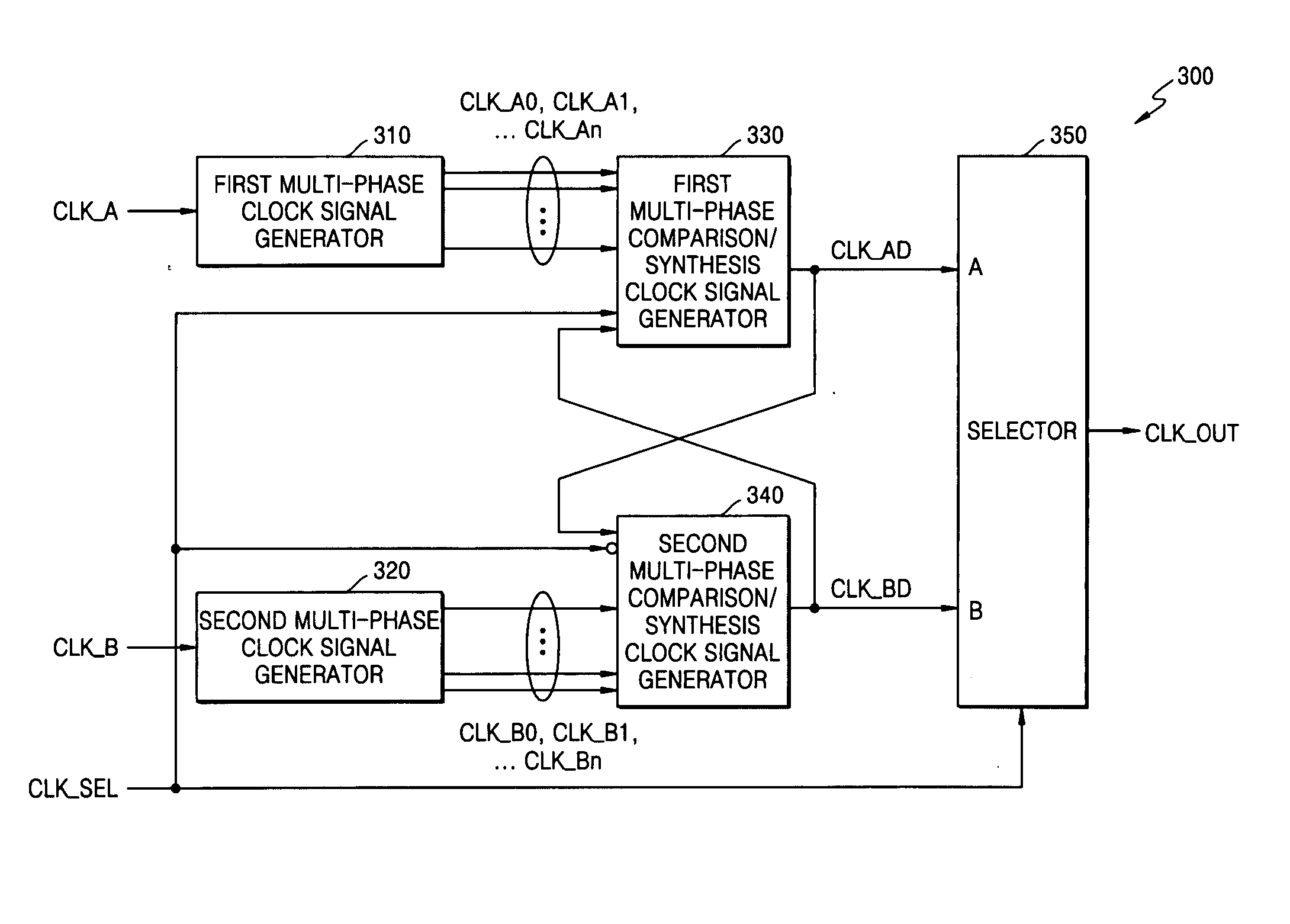
[0008] The present invention provides a clock signal selecting apparatus and method that can guarantee the continuity of an output clock signal even when switching a plurality of input clock signals from one to another by synchronizing the phases of the plurality of input clock signals with one another in real time.
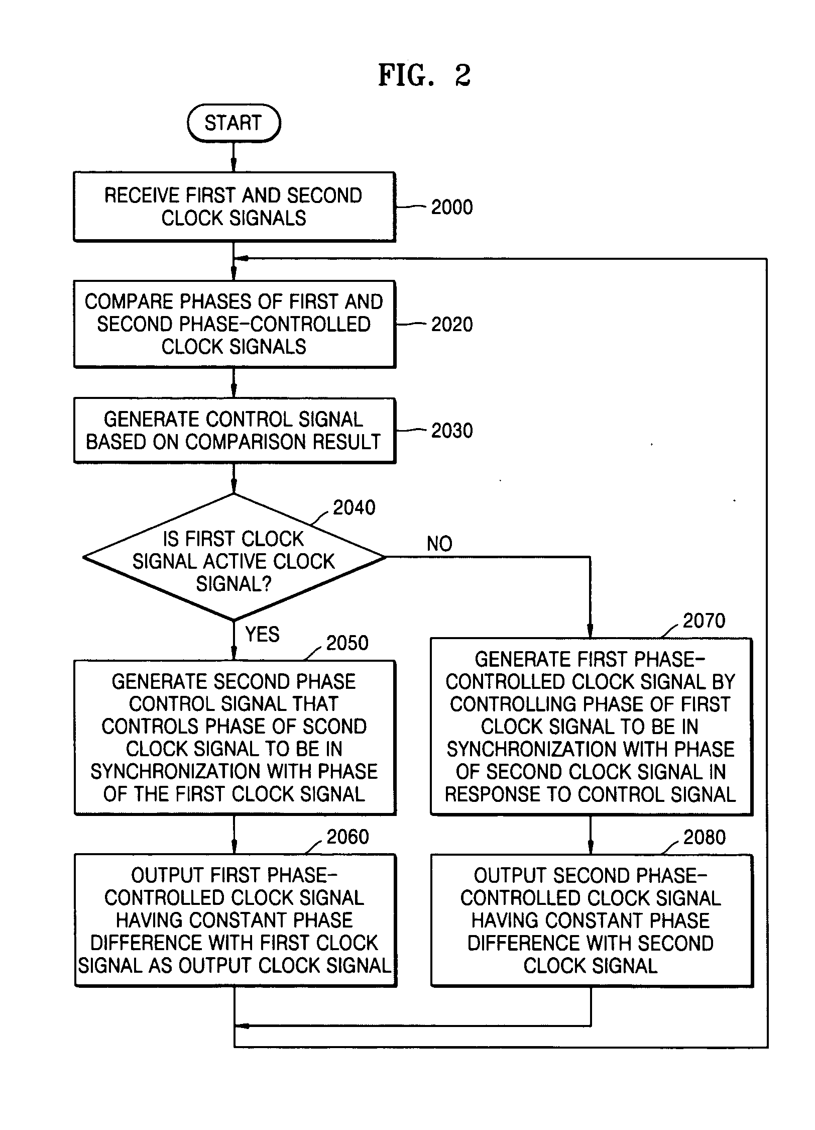
[0012] According to another aspect of the present invention, there is provided a clock signal selecting method that guarantees the continuity of an output clock signal. The clock signal selecting method involves (a) comparing the phases of N clock signals with the phase of one of the N clock signals, which is an active clock signal; (b) generating a control signal that controls the phase of each of the N clock signals to follow the phase of the predetermined clock signal; (c) generating N phase-controlled clock signals by controlling the phases of the N clock signals in response to the control signal; and (d) selecting one of the N phase-controlled clock signals corresponding to the active clock signal.

Problems solved by technology

However, the dual timing apparatus includes two timing devices disposed in different places and inevitably has a complicated circuit structure in order to synchronize clock signals output from the two timing devices with each other.
In this regard, the dual timing apparatus is not cost-effective, and it is difficult to distribute the clock signals from the two timing devices along the same path.

Method used


Image

  • Clock signal selecting apparatus and method that guarantee continuity of output clock signal
  • Clock signal selecting apparatus and method that guarantee continuity of output clock signal
  • Clock signal selecting apparatus and method that guarantee continuity of output clock signal

Examples


Embodiment Construction

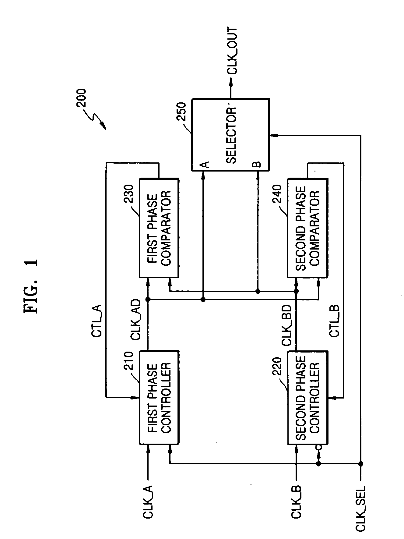
[0023]FIG. 1 is a block diagram illustrating a clock signal selecting apparatus 200 according to an exemplary embodiment of the present invention. Referring to FIG. 1, the clock signal selecting apparatus 200 includes a first phase controller 210, a second phase controller 220, a first phase comparator 230, and a second phase comparator 240, and a selector 250.

[0024] The first phase controller 210 receives a first clock signal CLK_A, which is one of two synchronization clock signals, a first control signal CTL_A, which is generated from the first phase controller 230, and a clock selection signal CLK_SEL and outputs a first phase-controlled clock signal CLK_AD. If the first clock signal CLK_A is set as a standby clock signal, the phase of the first phase-controlled clock signal CLK_AD output from the first phase controller 210 varies in response to the first control signal CTL_A. On the other hand, if the first clock signal CLK_A is set as an active clock signal, the first phase-co...


PUM


Abstract

Provided are a clock signal selecting apparatus and method that can guarantee the continuity of an output clock signal. The clock signal selecting apparatus and method can synchronize the phases of at least two clock signals by continuously controlling the phases of the clock signals. Accordingly, even when an active clock signal and a standby clock signal have different frequencies, it is possible to guarantee the continuity of the output clock signal regardless of whether the clock signals are switched from one to another. In addition, it is possible to guarantee the stability of the output clock signal.

Description

[0001] This application claims the priority of Korean Patent Application No. 2003-73444, filed on Oct. 21, 2003, in the Korean Intellectual Property Office, the disclosure of which is incorporated herein in its entirety by reference. BACKGROUND OF THE INVENTION [0002] 1. Field of the Invention [0003] The present invention relates to control of a clock signal, and more particularly, to a clock signal selecting apparatus and method that guarantee the continuity of an output clock signal. [0004] 2. Description of the Related Art [0005] Frequency synchronization is necessary between data transmission / communication systems and between devices in each of the data transmission / communication systems. Especially, for a high-speed / large-capacity data communication system or a high-precision frequency hierarchy-based data transmission system, frequency synchronization with the help of a timing device, such as a network synchronous device, is more than a requirement. [0006] In addition, devices...

Claims


Application Information

Patent Timeline
IPC IPC(8): G06F1/08H03D3/18H03K5/13H03L7/00H03L7/07
CPCG06F1/08H03K5/133H03L7/07H03L7/00
Inventor CHEUNG, TAE SIKLEE, BHUM CHEOLKIM, BONG TAE
Owner ELECTRONICS & TELECOMM RES INST
Learn More