
Planar-light source device and liquid crystal display apparatus having the same

a technology of light source device and liquid crystal display device, which is applied in mechanical devices, instruments, machines/engines, etc., can solve the problems of low uniformity of luminance between ccfl and led, increase in volume and weight, and drift current is not effectively prevented in the conventional planar-light source devi

Inactive Publication Date: 2005-04-21
SAMSUNG ELECTRONICS CO LTD
View PDF0 Cites 6 Cited by
  • Summary
  • Abstract
  • Description
  • Claims
  • Application Information

AI Technical Summary

Benefits of technology

[0016] The present invention provides a planar-light source device with partitions that prevent drift currents. The present invention also provides a liquid crystal display apparatus having the planar-light source device.
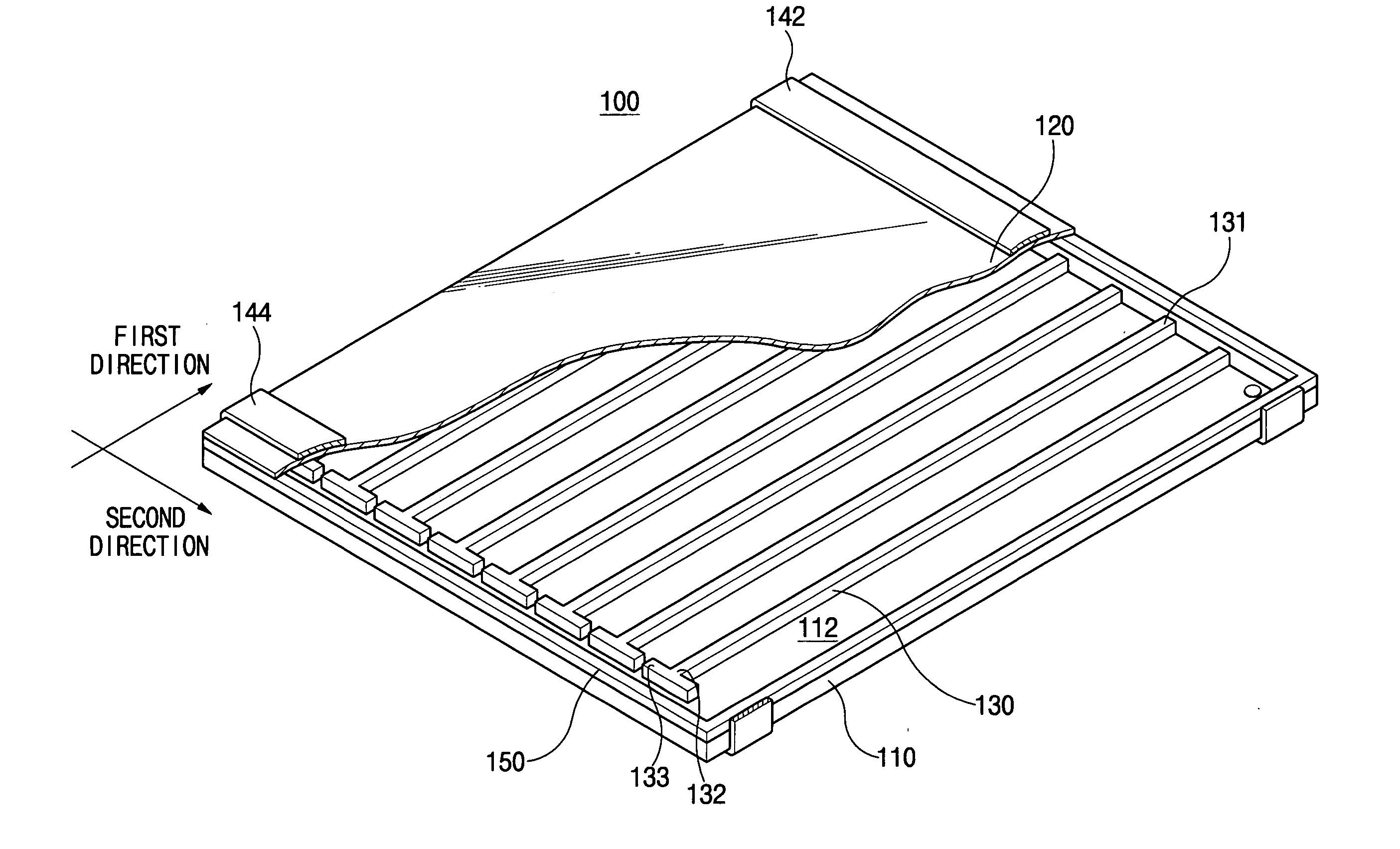
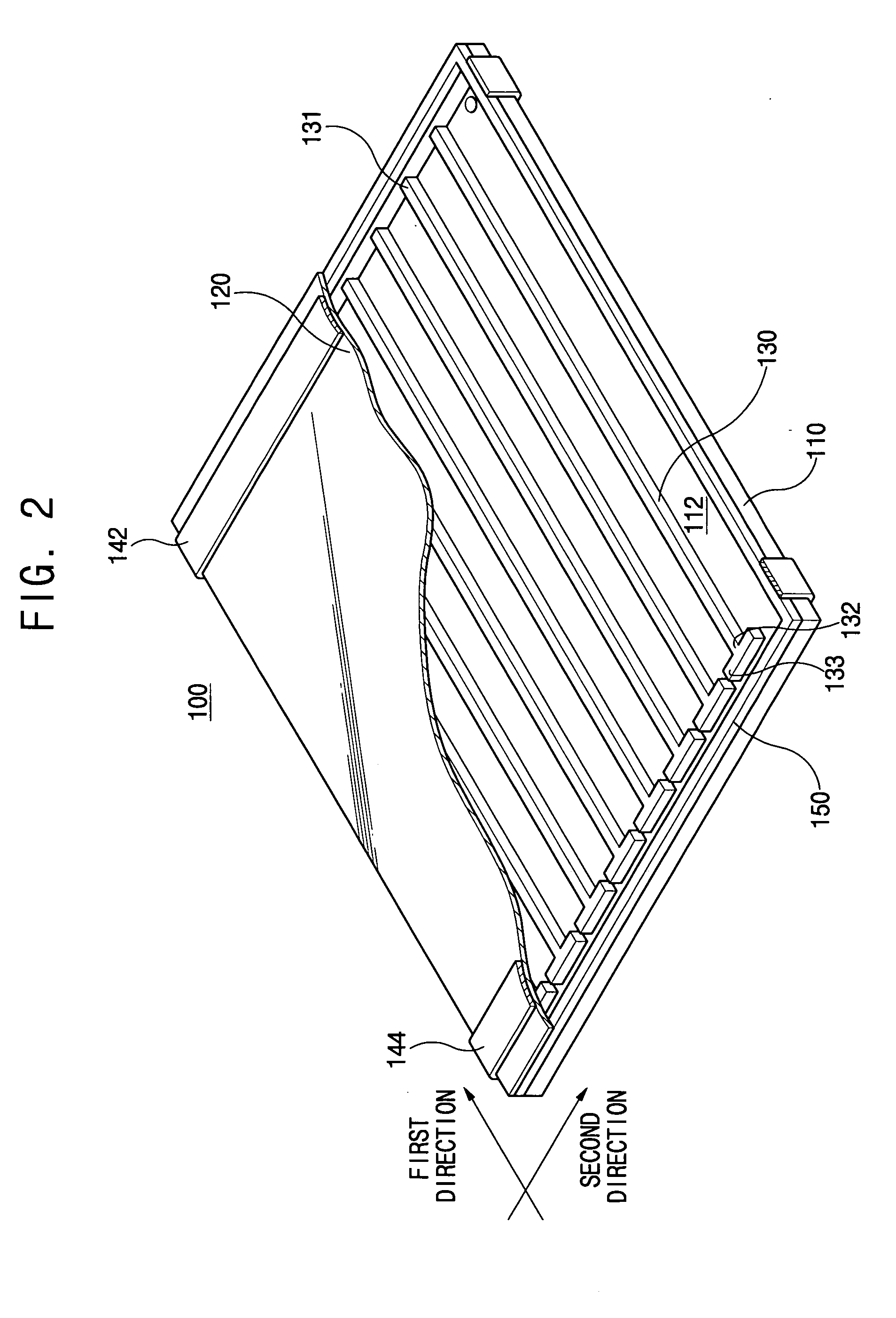
[0021] According to the present invention, plasma of one sub-space of the discharge space may not easily move to another sub-space of the discharge space. Thus, restricting the movement of plasma effectively prevents or reduces drift current, and connecting the sub-spaces of the discharge space in parallel reduces exhaustion time.

Problems solved by technology

However, both the CCFL and LED have low uniformity of luminance.
However, employment of these optical members causes an increase in volume and weight.
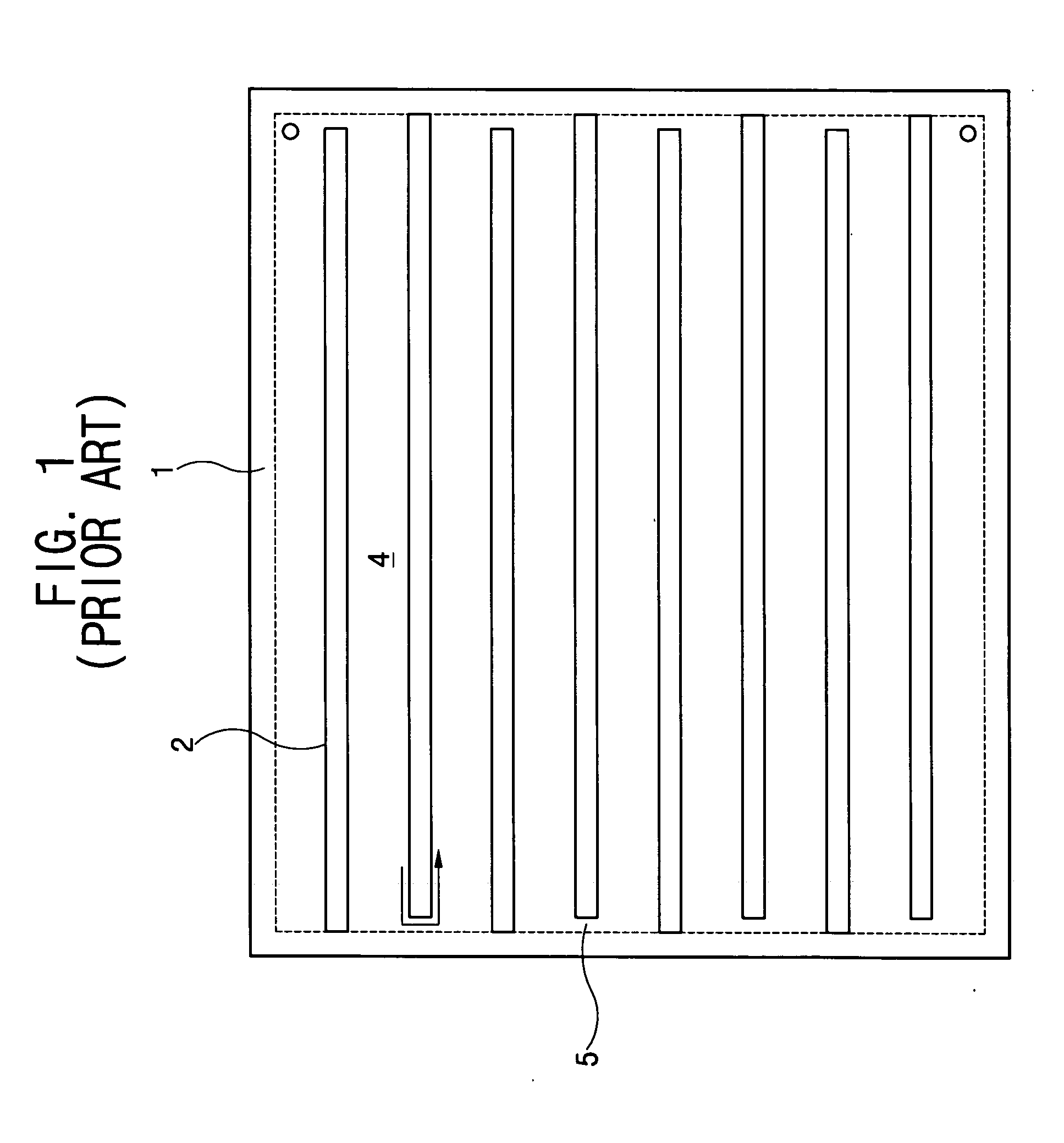
Therefore, a moving path of plasma, represented by the arrow symbol in FIG. 1, becomes short because the spaces between the partition members are directly connected with each other via the connection passage._As a result, drift current is not effectively prevented in the conventional planar-light source device.

Method used


Image

  • Planar-light source device and liquid crystal display apparatus having the same
  • Planar-light source device and liquid crystal display apparatus having the same
  • Planar-light source device and liquid crystal display apparatus having the same

Examples


sixth embodiment

[0080]FIG. 14 is a plan view illustrating a planar-light source device according to a seventh exemplary embodiment of the present invention. Referring to FIG. 14, the planar-light source device 600a is a modified embodiment of the sixth embodiment in FIG. 13 and includes a plate-shaped movement restriction member 633a. The plate-shaped movement restriction member 633a includes a plurality of connection holes 636a that connect the discharge space 612 and the path 635. The plate-shaped movement restriction member 633a is integrally formed with the partition members 630 at both the first and second ends thereof.

[0081]FIG. 15 is a plan view illustrating a planar-light source device according to an eighth exemplary embodiment of the present invention. Referring to FIG. 15, a planar-light source device 700 according to an eighth exemplary embodiment of the present invention includes partition members 730 having first and second ends 731 and 732 that are spaced apart from a sealing member ...

eighth embodiment

[0083]FIG. 16 is a plan view illustrating a planar-light source device according to a ninth exemplary embodiment of the preserit invention. Referring to FIG. 16, the planar-light source device 700a is a modified embodiment of the eighth embodiment in FIG. 15. The planar-light source device 700a includes movement restriction members 733a each having V-shaped arms each of which is extended in the second direction by a predetermined length. A connection passage 736a is formed between adjacent ones of the movement restriction members 733a to connect the discharge space and the path.

[0084] Alternately, the planar-light source device 700a may include one movement restriction member 733a disposed at each side of the partition members 730. In this case, two movement restriction members are provided such that one is connected with the first ends of the partition members and the other with the second ends of the partition members. The movement restriction members each have a corresponding con...


PUM


Abstract

A planar-light source device includes a light source body, partition members, a movement restriction member and an electrode. The light source body has a discharge space. The partition members are disposed in the discharge space to divide the discharge space into sub-spaces connected to each other. The movement restriction member is disposed at one of or both the side portions of the respective partition members to restrict plasma movement between the sub-spaces of the discharge space. The electrode surrounds the light source body, and is overlapped with the movement restriction member.

Description

BACKGROUND OF THE INVENTION [0001] 1. Field of the Invention [0002] The present invention relates to a light source device and a liquid crystal display apparatus, and more particularly, to a planar-light source device with partitions that prevent drift current and a liquid crystal display apparatus having the planar-light source device. [0003] 2. Description of the Related Art [0004] Generally, liquid crystal has specific electrical and optical characteristics. Arrangement of the liquid crystal is adjusted according to electric fields applied to the liquid crystal, and optical transmittance varies in accordance with the adjustment of the arrangement of the liquid crystal. [0005] A liquid crystal display (LCD) apparatus displays images using the specific electrical and optical characteristic of the liquid crystal. The LCD apparatus has many merits, such as a small volume, a lightweight, etc. Therefore, the LCD apparatus is used in various fields such as a portable computer, a liquid ...

Claims


Application Information

Patent Timeline
IPC IPC(8): G01D11/28G02F1/13357H01J61/30H01J65/04
CPCH01J65/046H01J61/305G02F1/1335
Inventor PARK, HAE-ILLEE, SANG-YUBYUN, JIN-SEOBKIM, HYOUNG-JOO
Owner SAMSUNG ELECTRONICS CO LTD
Learn More