
Image forming method and toner for use in the method

a technology of toner and forming method, which is applied in the direction of electrographic process, corona discharge, instruments, etc., can solve the problems of insufficient toner image fixation on the sheet, the temperature of the surface of the heating roller is apt to decrease, and the fixing method of the heating roller is not easy to achieve high-grade toner

Inactive Publication Date: 2005-04-14
RICOH KK
View PDF5 Cites 17 Cited by
  • Summary
  • Abstract
  • Description
  • Claims
  • Application Information

AI Technical Summary

Benefits of technology

It is an object of the present invention to provide an image forming method utilizing a heating roller fixation device and capable of producing high grade toner images at a wide range of the surface temperature of the heating roller.
It is a further object of the present invention to provide an image forming method capable of forming toner images having smooth surface, uniform image density and uniform gloss.

Problems solved by technology

The heating roller fixing method, however, has problems because a large thermal energy is absorbed by the transfer sheet such as paper during the contact of the image-bearing sheet with the heating roller.
Thus, when the preset temperature of the heating roller is low, the temperature of the surface of the heating roller is apt to decrease to bring about insufficient fixation of the toner image on the sheet.
While these toners have an effect in improving fixation efficiency, an improvement of image quality is not fully satisfactory.
However, when the toner image-bearing sheet is relatively thick, the toner image is crushed during fixation to cause deterioration of the image quality.
In particular, in the case of digital development, reproducibility of independent dots is adversely affected so that half tone portions of the image are not uniform microscopically.
Thus, when the image is observed with naked eyes, human observers are likely to have an impression of a roughness.

Method used

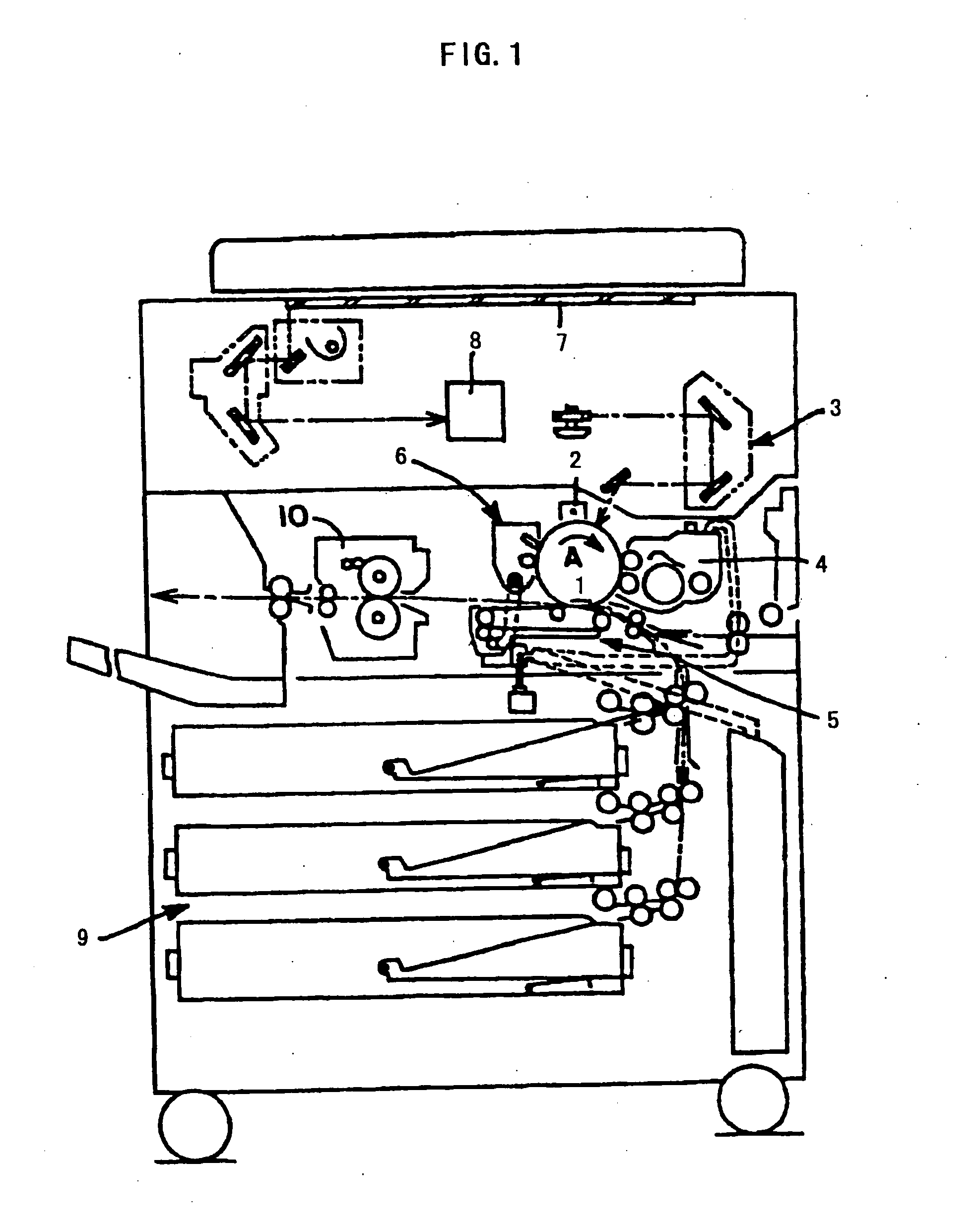
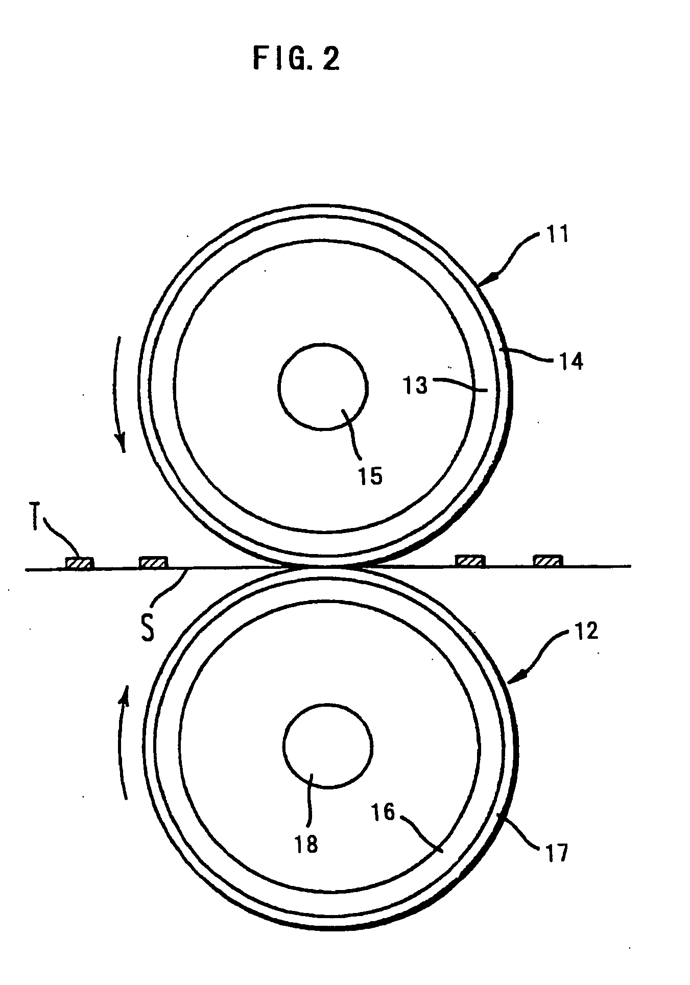
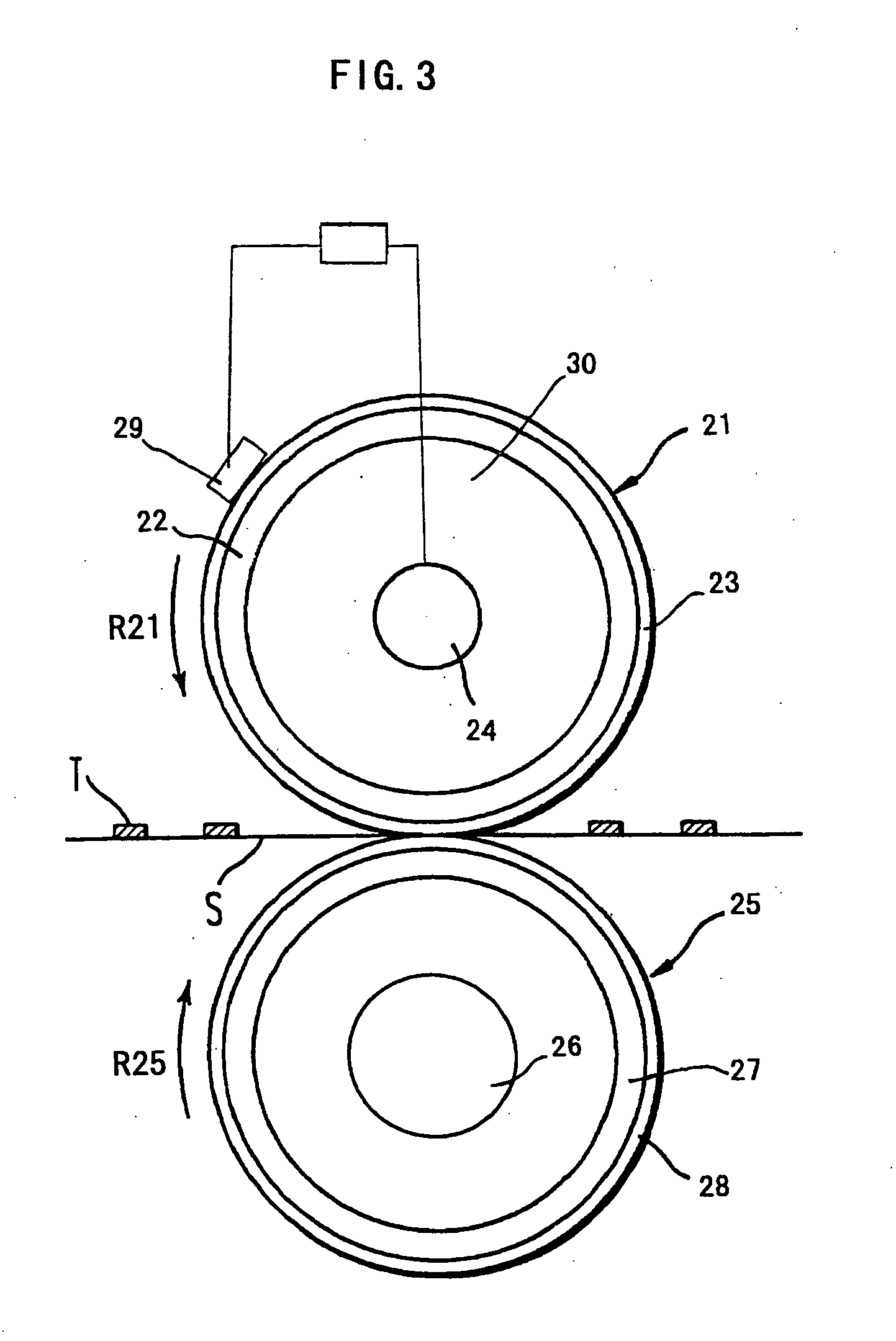

Image

  • Image forming method and toner for use in the method
  • Image forming method and toner for use in the method
  • Image forming method and toner for use in the method

Examples


example 1

Styrene-n-butyl acrylate copolymer75 parts(weight average molecular weight: 253,000)Styrene-n-butyl methacrylate copolymer10 parts(weight average molecular weight: 23,000)Carbon black (trade name: #44, manufactured10 partsby Mitsubishi Chemical Corp.Charge controlling agent (trade name: Spiron 2 partsBlack TR-H, manufactured by HodogayaChemical Corp.)Low molecular weight polyethylene 3 parts

The above components were mixed using a two axis kneader at 40° C. The kneaded mixture was cooled, pulverized and classified. The thus obtained mother toner had a weight average particle diameter of 10.5 μm. To the mother toner particles, 0.4 part of hydrophobic silica (R972 manufactured by Clariant Japan) as an external additive was mixed using Henschel mixer to obtain Toner (1). The Toner (1) was then mixed with a carrier which was obtained by coating ferrite particles having an average particle diameter of 80 μm with a silicone resin to obtain a Developer (1) having a toner content of 4% by w...

example 2

Styrene-butyl acrylate copolymer50 parts(weight average molecular weight: 350,000)Styrene-n-butyl methacrylate copolymer33 parts(weight average molecular weight: 39,000)Carbon black (trade name: #44, manufactured10 partsby Mitsubishi Chemical Corp.)Charge controlling agent (trade name: Spiron 2 partsBlack TR-H, manufactured by HodogayaChemical Corp.)Carnauba wax 5 parts

The above components were mixed using a two axis kneader at 110° C. The kneaded mixture was cooled, pulverized and classified. The thus obtained mother toner had a weight average particle diameter of 10.5 μm. To the mother toner particles, 0.4 part of hydrophobic silica (R972 manufactured by Clariant Japan) as an external additive was mixed using Henschel mixer to obtain Toner. (2). The Toner (2) was then mixed with a carrier which was obtained by coating ferrite particles having an average particle diameter of 80 μm with a silicone resin to obtain a Developer (2) having a toner content of 4% by weight. The thus obta...

example 3

Styrene-butyl acrylate copolymer53 parts(weight average molecular weight: 280,000)Styrene-2-ethylhexyl acrylate-n-butyl30 partsmethacrylate terpolymer(weight average molecular weight: 31,000)Carbon black (trade name: #44, manufactured10 partsby Mitsubishi Chemical Corp.)Charge controlling agent (trade name: Spiron 2 partsBlack TR-H, manufactured by HodogayaChemical Corp.)Carnauba wax 5 parts

The above components were mixed using a two axis kneader at 100° C. The kneaded mixture was cooled, pulverized and classified. The thus obtained mother toner had a weight average particle diameter of 10.5 μm. To the mother toner particles, 0.4 part of hydrophobic silica (R972 manufactured by Clariant Japan) as an external additive was mixed using Henschel mixer to obtain Toner (3). The Toner (3) was then mixed with a carrier which was obtained by coating ferrite particles having an average particle diameter of 80 μm with a silicone resin to obtain a Developer (3) having a toner content of 4% by ...


PUM

PropertyMeasurementUnit
volume change Vtaaaaaaaaaa
melt viscosityaaaaaaaaaa

Abstract

An image forming method, comprising passing a toner image-bearing sheet through a nip defined between two rollers including a heater roller to fix the toner image on the sheet, wherein the toner image is formed from a toner comprising a binder resin, and a colorant, wherein the toner image before the passage through the nip has a toner volume V1 and a toner image area S1, wherein the toner image after the passage through the nip has a toner volume V2 and a toner image area S2, and wherein a volume change Vt and an area change St defined by the formulas shown below are 30% or less and 20% or less, respectively: Vt(%)=(V1−V2) / V1×100 St(%)=(S2−S1) / S1×100. Alternatively, the toner image before the passage through the nip has a surface roughness of 2.5 μm or less.

Description

BACKGROUND OF THE INVENTION 1. Field of the Invention This invention relates to an image forming method in which toner images are formed by developing an electrostatic latent image by, for example, electrophotography, electrostatic recording or electrostatic printing, and to a toner useful for the image forming method. 2. Discussion of the Prior Art Various electrophotographic image forming methods have been disclosed in U.S. Pat. No. 2,297,691, Japanese Patent Publications Nos. 42-23910 and 43-24748. The methods typically include the following processes: (a) a surface of a photoconductor is charged (charging process); (b) the charged surface is exposed to light to form an electrostatic latent image thereon (latent image forming process); (c) the latent image is developed with a toner to form a toner image on the photoconductor (developing process); (d) the toner image is transferred directly or indirectly through an intermediate transfer member onto a transfer sheet such as pap...

Claims


Application Information

Patent Timeline
Patent Type & Authority Applications(United States)
IPC IPC(8): G03G9/08G03G9/087G03G13/20
CPCG03G9/0819G03G9/0821G03G9/08755G03G13/20G03G9/08795G03G9/08797G03G9/08793
Inventor AOKI, MITSUOHASEGAWA, KUMIHIGAYA, TOSHIAKIKOICHI, YASUSHITAKAHASHI, YUTAKAKASAI, TADASHI
Owner RICOH KK
Learn More