
Method of determining battery power limits for an energy storage system of a hybrid electric vehicle

a technology of hybrid electric vehicles and energy storage systems, which is applied in battery/fuel cell control arrangements, safety/protection circuits, transportation and packaging, etc., can solve the problems of limited amp-hour throughput of secondary batteries such as ni-mh batteries, and define their useful service life, so as to improve the robustness of overvoltage control

Active Publication Date: 2005-04-14
GM GLOBAL TECH OPERATIONS LLC
View PDF3 Cites 284 Cited by
  • Summary
  • Abstract
  • Description
  • Claims
  • Application Information

AI Technical Summary

Benefits of technology

[0011] This invention overcomes the deficiencies of the prior art by utilizing a closed loop controller with a warning track to determine the power limits for the ESS. The closed loop controller allows the power of the ESS to be available to the system that utilizes the ESS such that the voltage will be controlled precisely to the limit value under all operating conditions. In addition, the use of a warning track approach for determining the voltage limit value improves the robustness of the overvoltage control, particularly in cases of extreme temperature.

Problems solved by technology

For example, it is known that secondary batteries, such as Ni-MH batteries, have limited amp-hour throughput that defines their useful service life.

Method used


Image

  • Method of determining battery power limits for an energy storage system of a hybrid electric vehicle
  • Method of determining battery power limits for an energy storage system of a hybrid electric vehicle
  • Method of determining battery power limits for an energy storage system of a hybrid electric vehicle

Examples


Embodiment Construction

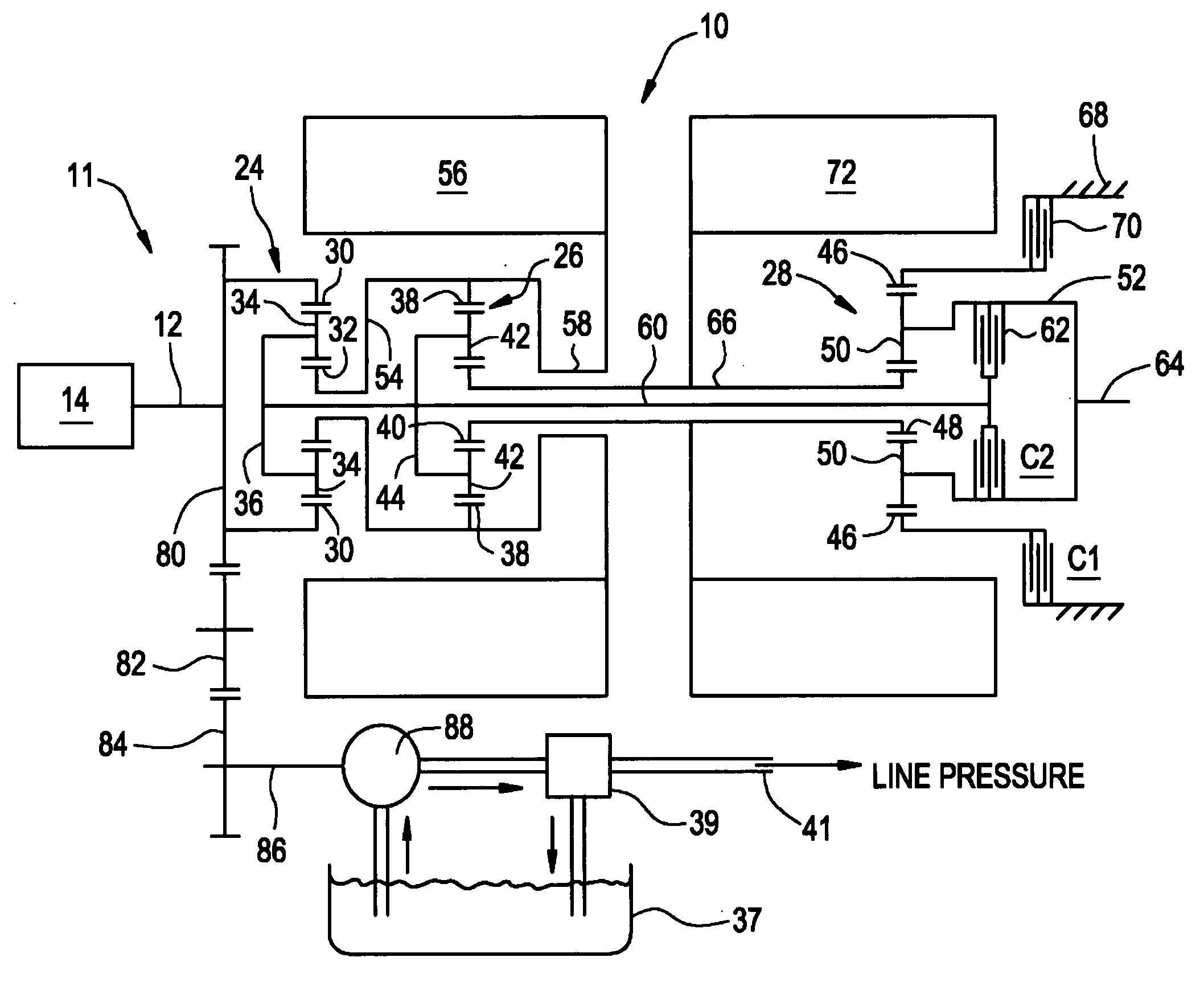
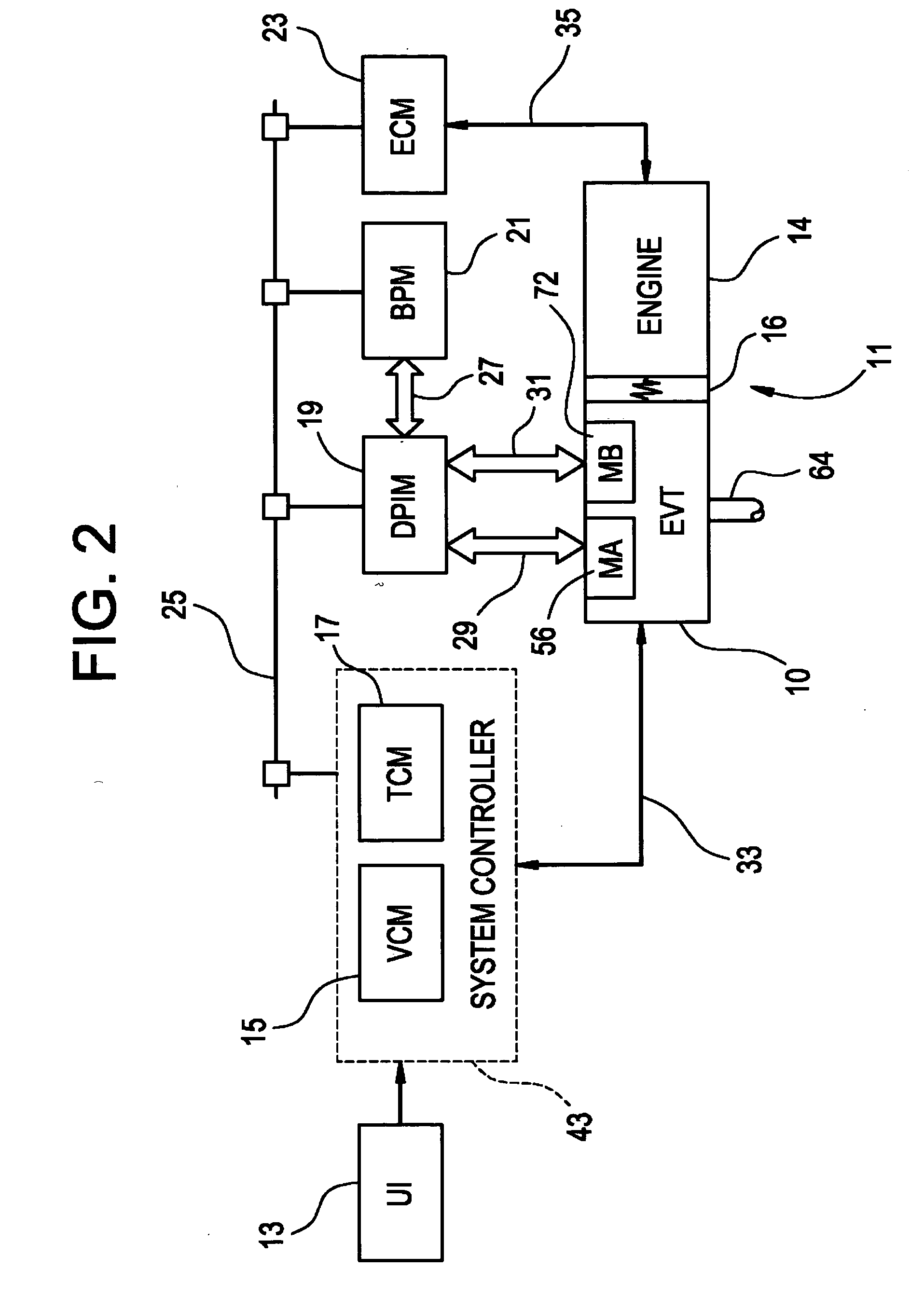
[0033] With reference first to FIGS. 1 and 2, a vehicular powertrain is generally designated 11. Included in the powertrain 11 is one representative form of a multi-mode, compound-split, electrically variable transmission (EVT) particularly suited for implementing the controls of the present invention and designated generally by the numeral 10 in FIGS. 1 and 2. With particular reference, then, to those figures, the EVT 10 has an input member 12 that may be in the nature of a shaft which may be directly driven by an engine 14 or, as shown in FIG. 2, a transient torque damper 16 may be incorporated between the output member of the engine 14 and the input member of the EVT 10. The transient torque damper 16 may incorporate, or be employed in conjunction with, a torque transfer device (not shown) to permit selective engagement of the engine 14 with the EVT 10, but it must be understood that such a torque transfer device is not utilized to change, or control, the mode in which the EVT 10...


PUM


Abstract

A method of providing closed-loop control of power flowing into and out of an energy storage system (ESS), wherein the ESS comprises a battery is provided. The method may be implemented as a computer control algorithm for determining the charge and discharge limits for the ESS in a hybrid electric vehicle (HEV), wherein the ESS comprises a battery pack or array. The method comprises determining charge and discharge power limits during each of a plurality of control loops, comparing these limits during each of the plurality of control loops, and providing a charge power limit output and a discharge power limit output for use in a subsequent control loop which are based upon the charge power limit and the discharge power limit. The charge power limit output and discharge power limit output are set equal to the discharge power limit and charge power limit, respectively, when the discharge power limit is greater than the charge power limit; and are selected from the group consisting of the charge power limit, the discharge power limit and zero when the discharge power limit is less than or equal to the charge power limit.

Description

TECHNICAL FIELD [0001] This invention comprises a method for controlling the energy storage system (ESS) in a hybrid electric vehicle (HEV). More particularly, the method comprises a computer control algorithm for determining the charge and discharge limits for the battery in an HEV, such that it is protected from damage and yet is capable of maximum available utilization. BACKGROUND OF THE INVENTION [0002] An HEV is a vehicle that has a propulsion system that consists of at least one electric motor or electric machine in combination with at least one other power source. Typically, the other power source is a gasoline or diesel engine. There are various types of HEVs depending on how the electric motor(s) and other power source(s) are combined with one another in order to provide propulsion for the vehicle, including series, parallel and compound HEVs. [0003] Various hybrid powertrain architectures are known for managing the input and output torques of various propulsion systems in ...

Claims


Application Information

Patent Timeline
IPC IPC(8): B60L11/18B60W10/26B60W20/00H02J7/00H02J7/04
CPCB60K6/445B60L11/1861B60W10/26B60W20/102Y02T10/6239H02J7/0047Y02T10/7005Y02T10/7044Y02T10/705H02J7/0029B60W20/11B60L58/12Y02T10/62Y02T10/70H02J7/00308H02J7/0048
Inventor CAWTHORNE, WILLIAM R.WEST, STEVE T.
Owner GM GLOBAL TECH OPERATIONS LLC
Learn More