
On-signal quadrature modulator calibration

Active Publication Date: 2005-04-07
INTELLECTUAL VENTURES I LLC
View PDF3 Cites 53 Cited by
  • Summary
  • Abstract
  • Description
  • Claims
  • Application Information

AI Technical Summary

Problems solved by technology

The combined digital signal must then be converted to an analog signal prior to up-conversion and transmission, which generates an undesired image that is difficult and expensive to eliminate.
The analog processing components are not perfectly matched, so that several types of distortion are introduced into the signal path.
These distortions include DC offsets and amplitude and phase imbalances.
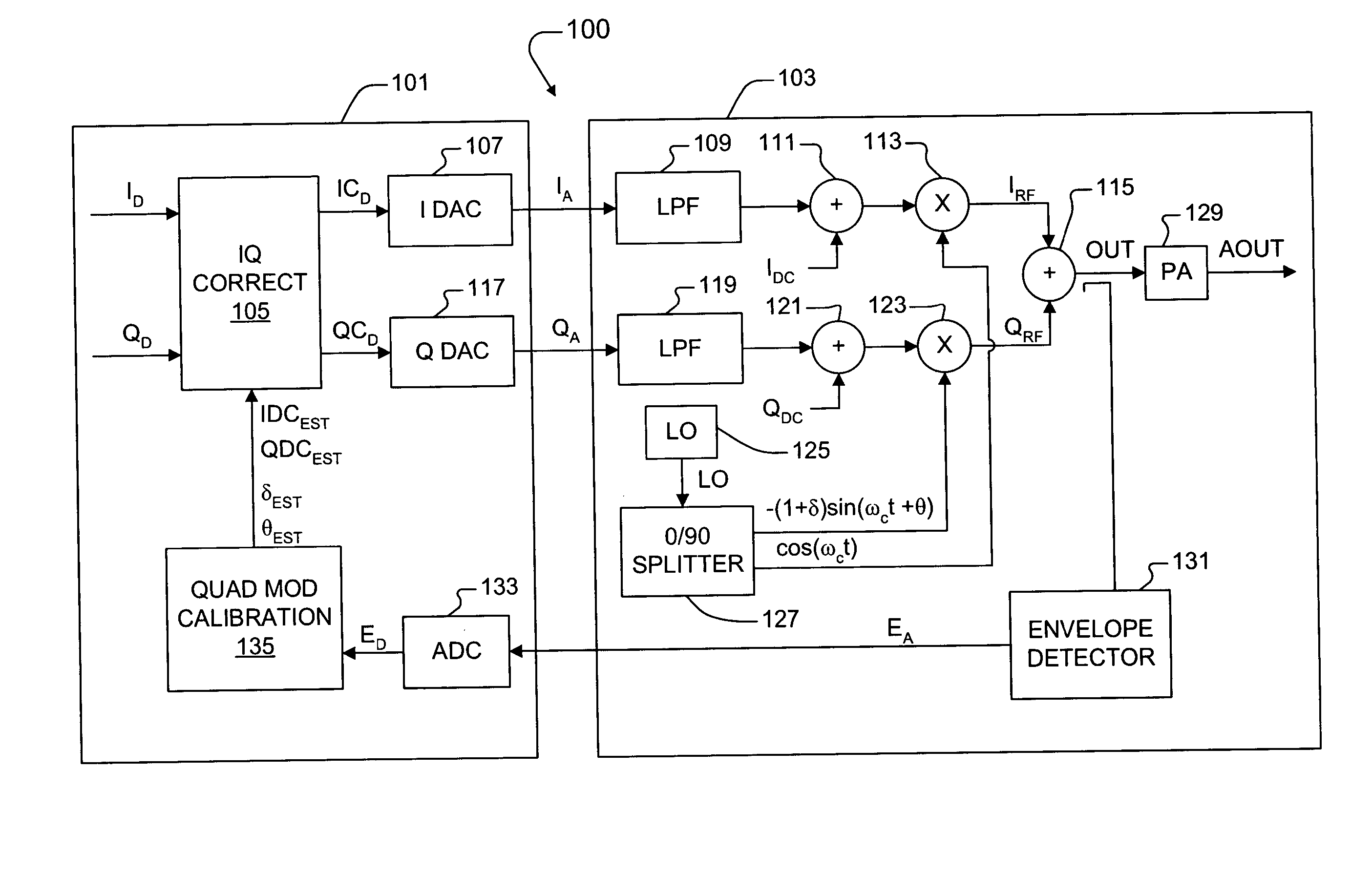
The local oscillator (LO) splitter carrier signals and the mixer stages are not perfectly matched resulting in amplitude and phase imbalances that cause distortions in the transmitted signal.
The distortions, caused by DC, amplitude and phase imbalances, degrade the performance of digital communication systems including systems employing digital signal processing (DSP) techniques.
Amplitude and phase imbalances cause variations in constellation plots that degrade communication effectiveness.
Large gain or phase imbalances can effectively disable reliable communications, particularly higher density modulation techniques used to achieve higher data transmission rates.
Imbalances, however, can drift over time due to various factors including, for example, temperature and aging.
Static compensation at the time of manufacture does not address the dynamic factors that affect radio operation during use.
Such off-line methods degrade overall system efficiency by consuming valuable time to perform calibration and compensation.
Vital packets may be missed during the calibration process since the antenna(s) must be disconnected or otherwise disabled to prevent inadvertent transmissions.
Some calibration techniques negatively impact the wireless medium, such as undesirable signal splattering.

Method used


Image

  • On-signal quadrature modulator calibration
  • On-signal quadrature modulator calibration
  • On-signal quadrature modulator calibration

Examples


Embodiment Construction

[0031] The following description is presented to enable one of ordinary skill in the art to make and use the present invention as provided within the context of a particular application and its requirements. Various modifications to the preferred embodiment will, however, be apparent to one skilled in the art, and the general principles defined herein may be applied to other embodiments. Therefore, the present invention is not intended to be limited to the particular embodiments shown and described herein, but is to be accorded the widest scope consistent with the principles and novel features herein disclosed.

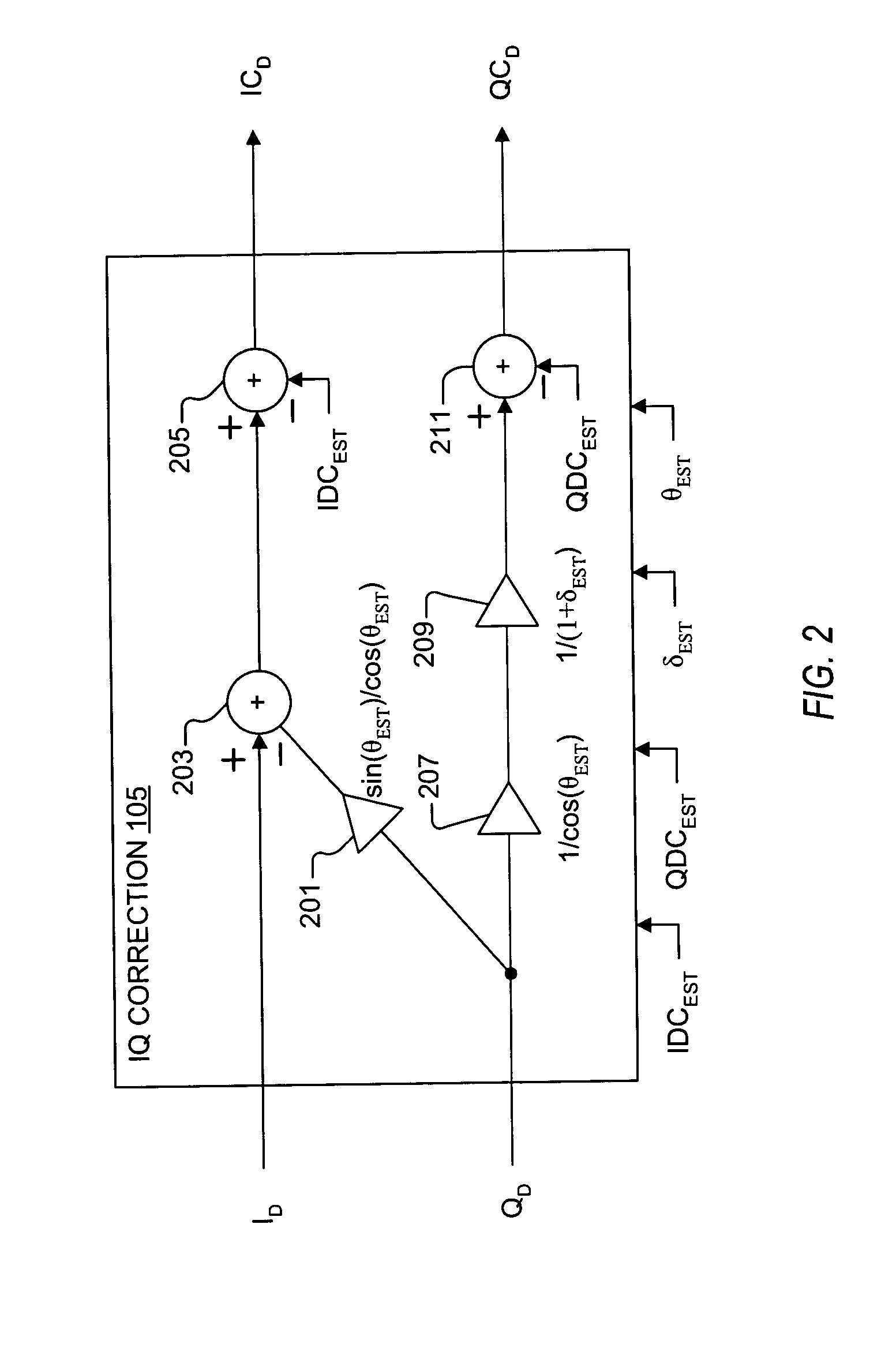
[0032] The inventors of the present application have recognized the need for calibrating the modulator of a transmitter. They have therefore developed an on-signal quadrature modulator calibration system and method that calibrates the modulator in real-time while transmitting actual signals without the need for separate calibration cycles, as will be further described below w...


PUM


Abstract

An on-signal calibration system I and Q signals of a transmitter to remove distortions in the RF output signal. The transmitter generates I and Q values and converts, modulates and combines the I and Q values into the RF output signal for transmission. The calibration system includes a detector, a sampler, a selector, an imbalance estimator, and an IQ corrector. The detector senses the RF output signal and provides a detection signal indicative thereof. The sampler samples the detection signal and provides digital samples. The selector selects from among the digital samples that correspond to predetermined ranges of the I and Q values, or otherwise predetermined selection boxes at predetermined phases. The imbalance estimator determines at least one imbalance estimate based on selected digital samples. The IQ corrector corrects the I and Q values using at least one imbalance estimate.

Description

BACKGROUND OF THE INVENTION [0001] 1. Field of the Invention [0002] The present invention relates to calibration of a transmitter to remove distortions, and more particularly to on-signal quadrature modulator calibration using an output signal detector to remove DC, phase and amplitude imbalances. [0003] 2. Description of the Related Art [0004] Many modern communications systems combine in-phase (I) and quadrature phase (Q) components in a transmitted signal. The I and Q components can be generated and combined in the digital domain without distortion. The combined digital signal must then be converted to an analog signal prior to up-conversion and transmission, which generates an undesired image that is difficult and expensive to eliminate. Alternatively, the I and Q components may be separately converted to analog signals, which are then combined in the analog domain. The analog processing components are not perfectly matched, so that several types of distortion are introduced int...

Claims


Application Information

Patent Timeline
IPC IPC(8): H04B17/00
CPCH03C3/406H03D3/008H04B17/14H04L27/364H03D3/009
Inventor WEBSTER, MARK A.SEALS, MICHAEL J.COCHRAN, BRUCE A.
Owner INTELLECTUAL VENTURES I LLC
Learn More