Eureka AIR delivers breakthrough ideas for toughest innovation challenges, trusted by R&D personnel around the world.

Portable gas fractionalization system

a gas fractionalization and portable technology, applied in the direction of respirators, separation processes, other medical devices, etc., can solve the problems of reducing the efficiency of air flow, and reducing the noise generated by air flow

Inactive Publication Date: 2005-04-07
INOGEN INC
View PDF99 Cites 67 Cited by
  • Summary
  • Abstract
  • Description
  • Claims
  • Application Information

AI Technical Summary

Benefits of technology

[0007] In one aspect, the preferred embodiments of the present-invention provide a portable gas fractionalization apparatus comprising a compressor which compresses a gas, such as air, to provide a feed gas; plural adsorbent beds which receive said feed gas and output a purified gas and a waste gas; a battery which supplies power to said compressor; and a housing which comprises an ambient air inlet, an ambient air outlet, and plural compartments. Preferably, a first of the compartments contains the adsorbent beds and a second of the compartments contains the compressor, wherein the compartments significantly inhibit migration of thermal energy from the second compartment to the first compartment. In one embodiment, the apparatus further comprises an air circulation fan which draws air through the inlet into the first compartment, and through the first compartment into the second compartment, the air being exhausted through the outlet. Preferably, the fan is positioned directly above the compressor and produces an air stream directly against the compressor.
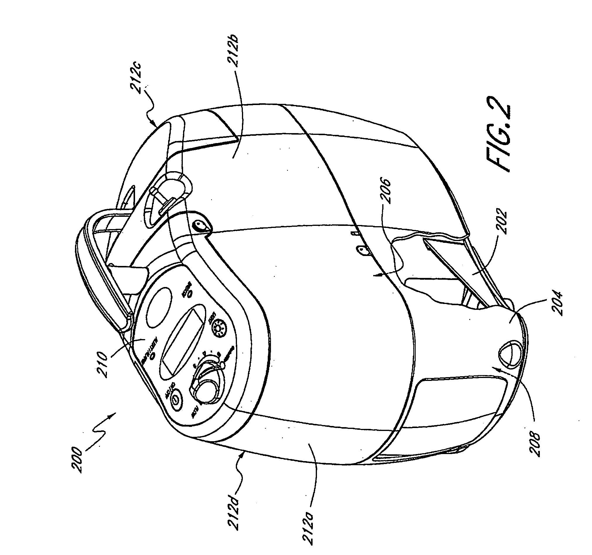
[0009] In a second aspect, the preferred embodiments of the present invention provide a portable gas fractionalization apparatus which includes a housing comprised of a chassis and a shell. The apparatus further includes a plurality of components mounted on and structurally supported by the chassis. Preferably, the shell covers the components and is removable from the chassis without removing the components. In one embodiment, the shell has a plurality of sidewalls, wherein at least one sidewall has a concave or convex section that provides curvature to the sidewall so as to reduce coupling of sound or vibration energy generated by components in the housing. In another embodiment, the shell has an opening adapted to receive a filter which filters fluid output from the apparatus wherein the filter is accessible from the exterior of the shell. Moreover, the chassis preferably comprises a plurality of integral structures adapted to receive and support the components, such as an integral compressor mount, an integral battery slot, and at least one integral gas flow passageway. Preferably, the chassis provides an intermediary vibration isolation between the components and the shell of the housing. In certain embodiments, the housing further includes a hatch that is removably attached to the shell to provide access to one or more components therein.
[0011] In a fourth aspect, the preferred embodiments of the present invention provide a method of producing oxygen. The method comprises providing an oxygen concentrator having an air compressor which supplies compressed air to a PSA unit comprising plural adsorbent beds and a plurality of valves which control fluid flow to and from the beds; generating an air flow through the concentrator by inputting air through an inlet and outputting the air through an outlet, such that the air flows along a flow path through the concentrator; and exposing the valves to an upstream portion of the flow path and exposing the air compressor to a downstream portion of the flow path, such that the valves are substantially isolated from air that flows through the downstream portion of the flow path. Preferably, the air flow is generated using an air circulation fan to produce an air stream directly against the air compressor. In one embodiment, the method further comprises directing the air flow to flow along a circuitous flow path through the concentrator. Preferably, the air in the downstream portion of the flow path is substantially inhibited from circulating back into the upstream portion. In one embodiment, the method further comprises providing a plurality of sound baffles along at least a portion of the air flow path to reduce noise generated by the air flow and guide the air flow along the flow path.

Problems solved by technology

Thus, patients usually cannot leave home for any length of time unless they carry with them additional cylinders, which can be heavy and cumbersome.
Patients who wish to travel often have to make arrangements with medical equipment providers to arrange for an exchange of cylinders at their destination or along the route, the inconvenience of which discourages many from taking extended trips away from home.
While oxygen concentrators are effective at continual production of oxygen, they are typically large electrically powered, stationary units that generate high levels of noise, in the range of 50-55 dB, which presents a constant source of noise pollution.
Moreover, the units are too heavy to be easily transported for ambulatory use as they typically weigh between 35 to 55 lbs.
Patients who use oxygen concentrators are thus tethered to the stationary machines and inhibited in their ability to lead an active life.
While portable oxygen concentrators have been developed to provide patients with greater mobility, the currently commercially available portable concentrators do not necessarily provide patients with the ease of mobility that they desire.
The portable concentrators tend to generate as much noise as the stationary units and thus cannot be used at places such as the theater or library where such noise is prohibited.
Moreover, the present portable concentrators have very short battery life, typically less than one hour, and thus cannot be used continuously for any length of time without an external power source.

Method used


Image

  • Portable gas fractionalization system
  • Portable gas fractionalization system
  • Portable gas fractionalization system

Examples


Embodiment Construction

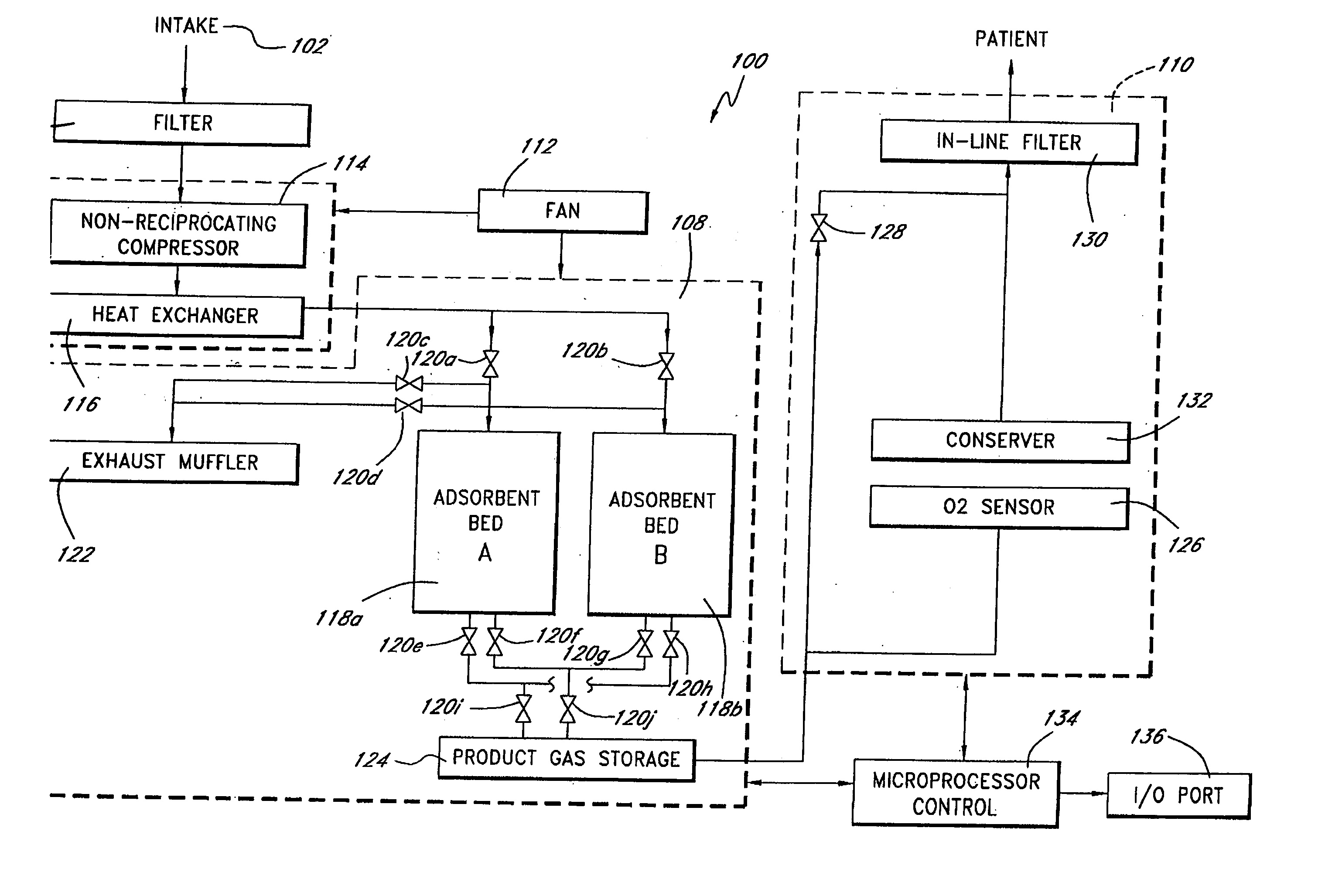
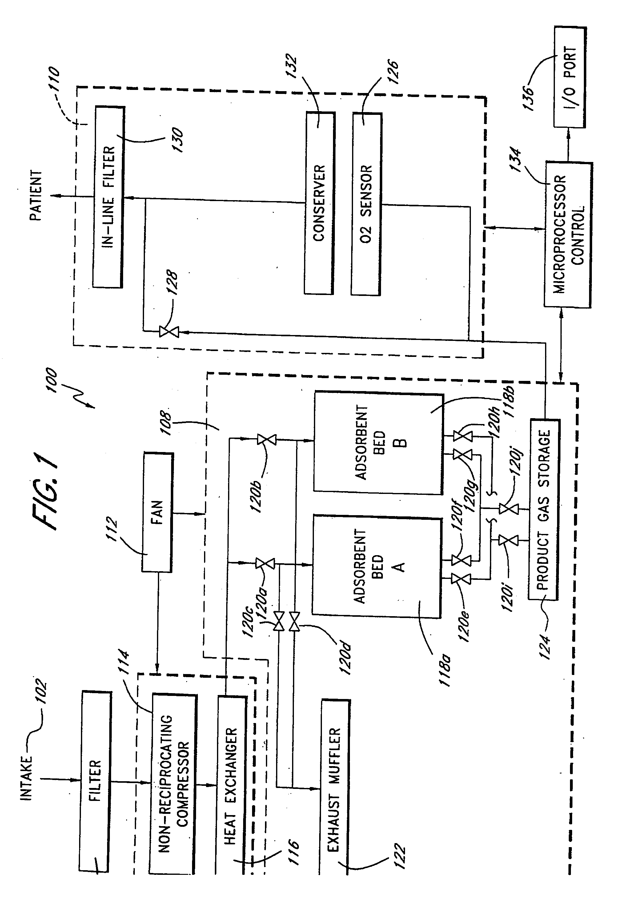
[0032]FIG. 1 schematically illustrates a portable gas fractionalization system 100 of one preferred embodiment of the present invention. As shown in FIG. 1, the system 100 generally comprises an intake 102 through which ambient air is drawn into the system, a filter 104 for removing particulate from the intake air, a compressor assembly 106 for pressurizing the intake air to provide a feed gas, a pressure swing adsorption (PSA) unit 108 which receives and processes the feed gas to produce a product gas having a higher oxygen content than the ambient air, and a gas delivery system 110 for delivering the product gas to a patient.

[0033] Ambient air is drawn through the intake 102 at a relatively low flow rate, preferably no greater than about 15 standard liters per minute (slpm), so as to reduce noise due to airflow through the system. The system 100 further includes a fan 112 that produces an air stream across the compressor assembly 106 also preferably at a relatively low flow rate ...


PUM

PropertyMeasurementUnit
Flow rateaaaaaaaaaa
Sensitivityaaaaaaaaaa
Energyaaaaaaaaaa

Abstract

A portable gas fractionalization apparatus that provides oxygen rich air to patients is provided. The apparatus is compact, lightweight, and low-noise. The components are assembled in a housing that is divided into two compartments. One compartment is maintained at a lower temperature than the other compartment. The lower temperature compartment is configured for mounting components that can be damaged by heat. The higher temperature compartment is configured for mounting heat generating components. An air stream is directed to flow from an ambient air inlet to an air outlet constantly so that there is always a fresh source of cooling air. The apparatus utilizes a PSA unit to produce an oxygen enriched product. The PSA unit incorporates a novel single ended column design in which all flow paths and valves can be co-located on a single integrated manifold. The apparatus also can be used in conjunction with a satellite conserver and a mobility cart.

Description

BACKGROUND OF THE INVENTION [0001] 1. Field of the Invention [0002] This invention relates generally to a portable gas fractionalization system, more particularly, to a compact oxygen concentrator that is suitable for both in-home and ambulatory use so as to provide users greater ease of mobility. [0003] 2. Description of the Related Art [0004] Patients who suffer from respiratory ailments such as Chronic Obstructive Pulmonary Diseases (COPD) often require prescribed doses of supplemental oxygen to increase the oxygen level in their blood. Supplemental oxygen is commonly supplied to the patients in metal cylinders containing compressed oxygen gas or liquid oxygen. Each cylinder contains only a finite amount of oxygen that typically lasts only a few hours. Thus, patients usually cannot leave home for any length of time unless they carry with them additional cylinders, which can be heavy and cumbersome. Patients who wish to travel often have to make arrangements with medical equipment...

Claims


Application Information

Patent Timeline
IPC IPC(8): A61M16/10B01D53/04B01D53/047
CPCA61M2205/8206A61M2209/084B01D53/0407B01D53/047A61M16/101B01D2256/12B01D2257/102B01D2259/402B01D2259/4533B01D2253/108A61M2016/1025A61M2202/0208A61M2202/03A61M16/107A61M2202/0007
Inventor DEANE, GEOFFREY FRANKTAYLOR, BRENTON ALANBARE, REX O.SCHERER, ANDREW J.
Owner INOGEN INC
Why Eureka
Eureka Blog
Learn More