
Method and system for monitoring power supplies

a power supply and monitoring system technology, applied in power supply testing, measurement using digital techniques, instruments, etc., can solve problems such as system failure, equipment failure, equipment failure, etc., and achieve the effect of saving equipment, data loss, and emergency service response tim

Inactive Publication Date: 2005-03-31
STEFAN DONALD A
View PDF2 Cites 126 Cited by
  • Summary
  • Abstract
  • Description
  • Claims
  • Application Information

AI Technical Summary

Problems solved by technology

When batteries in this type of equipment fail, this can cause disruption in related operations.
Without constant monitoring of the condition of the batteries, customers may expect to experience battery deterioration and eventually a battery failure at some point in time.
A system failure can be extremely expensive in lost data, equipment, and emergency service response (down) time.
Users of Uninterruptible Power Supplies currently face the choice of either replacing batteries at short specified intervals, waiting for a battery failure, which can have catastrophic consequences, or have periodic load tests performed by a field service engineer.
It increases the cost of the system over a period of time while creating extra work and expense for the customer, including the hidden expense of environmentally approved battery disposal.
They are expensive and disruptive.
Electrical power from public utility companies has been found to be a source of disruptions in the operations of many companies.
With the increase in a public utility's overall load, the lack of new power generating plants coming on-line, and the deregulation of utility companies, these problems of interruptions will most likely continue to increase over the foreseeable future.
UPS systems are installed to help compensate for power failures, but these can become an expensive sacrificial device in the circuit or they can introduce new problems into the electrical power distribution.
Many power related problems can also come from within a customer's facility, whether it is in a building owned by them or leased space.
Since the business environment changes over time, any power survey provided at a single point in time will not necessarily provide adequate information to show that electrical power may be the source of computer problems, for example.
A monitoring system consisting of hardware and software alone is not adequate.

Method used


Image

  • Method and system for monitoring power supplies
  • Method and system for monitoring power supplies
  • Method and system for monitoring power supplies

Examples


Embodiment Construction

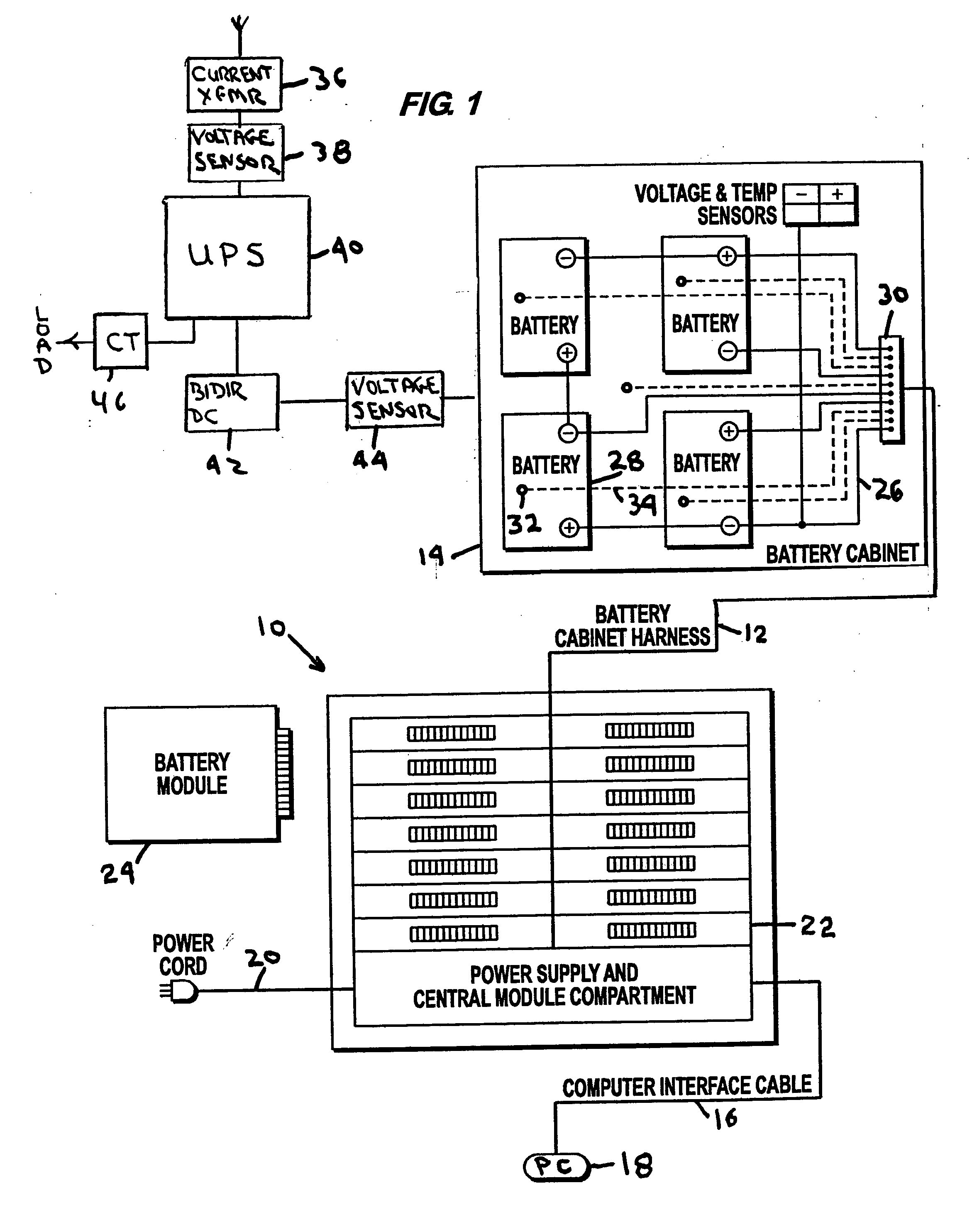
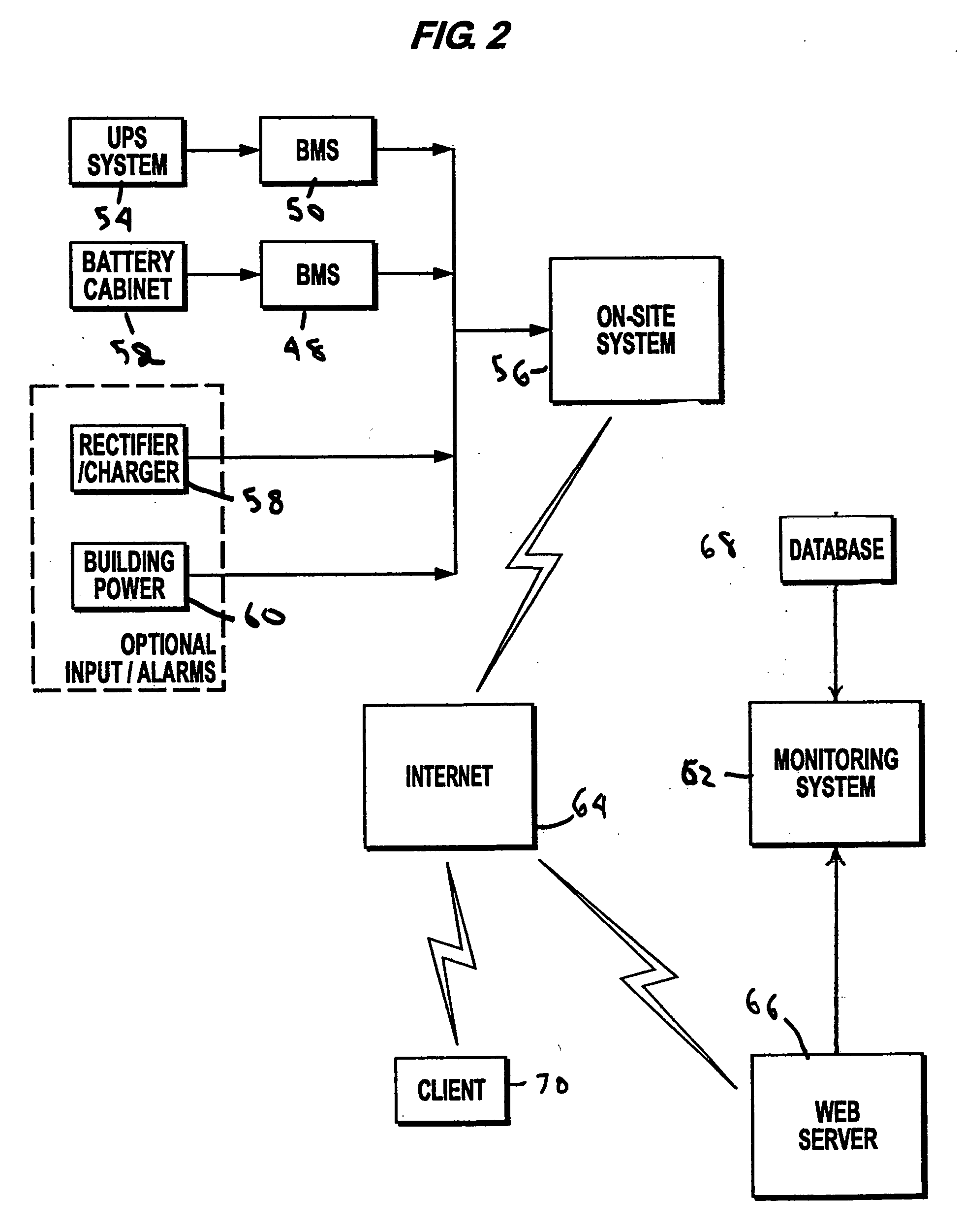
[0015] There is a great need to provide the customer with a full time measurement and trending of their UPS and DC plant batteries as well as incoming electrical power from a public utility. A Battery Monitoring System (BMS), such as that shown in the Figures, provides DC measurements in “near” real time providing up to the minute, continual measurements during the battery's three states, float, discharge, and recharge. Each of these measurements is needed to accurately determine the integrity of individual batteries in any type of battery system. Constant measurement provides the required measurement data to build a curve with enough resolution to “chart” the battery. As a “virtual technician” the BMS system provides this capability for each battery in a system and under all conditions. In addition to monitoring the DC voltage at each battery, the system looks at: the system's battery charger; individual battery temperature; ambient temperature; equipment load; and incoming electri...


PUM


Abstract

An electrical power (AC / DC) monitoring system remotely monitoring batteries and electrical power systems through a call center, providing continual monitoring, monthly reports, near real time viewing and service response. Modular by design, a plurality of individual input modules, which receive an analog voltage input, convert this signal to a digital format and send the digital signal to a central control which collects the data, then, at scheduled intervals, sends the collected data to a web server which contains the main software for the system. This software performs data comparisons, charts trends, predicts failures, plans and schedules service visits, then archives the data for future references. Alarm notifications are provided to the customer via Email, office phone (land line), cell phone (wireless), PDA, pager, etc. and can also be sent to a service provider to initiate the service response.

Description

BACKGROUND OF THE INVENTION [0001] 1. The Field of the Invention [0002] The present invention pertains to a method and system to remotely monitor batteries and electrical power supplies to anticipate potential problems and effect a solution prior to any destructive power failure. [0003] 2. The Prior Art [0004] Uninterruptible Power Supplies (UPS), Telecommunications and Instrumentation DC Power Systems utilize batteries, typically lead acid batteries of either sealed or flooded design, as a backup power supply. When batteries in this type of equipment fail, this can cause disruption in related operations. Without constant monitoring of the condition of the batteries, customers may expect to experience battery deterioration and eventually a battery failure at some point in time. A system failure can be extremely expensive in lost data, equipment, and emergency service response (down) time. [0005] In every day operations there is an ongoing concern about the condition of batteries whi...

Claims


Application Information

Patent Timeline
IPC IPC(8): G01R19/25G01R31/40G06F19/00
CPCG01R19/2513G01R31/3689G01R31/40G01R31/371
Inventor STEFAN, DONALD A.
Owner STEFAN DONALD A
Learn More