Protected dual purpose power/enter switch apparatus and method

Active Publication Date: 2005-03-31
NYTELL SOFTWARE LLC
View PDF30 Cites 0 Cited by
  • Summary
  • Abstract
  • Description
  • Claims
  • Application Information

AI Technical Summary

Benefits of technology

[0010] In one embodiment, the apparatus of the invention is comprised of a switch, two relays, and a microprocessor all of which are adapted to interact with a motherboard for any device, particularly an integrated receiver decoder for digital data transmission. When the device is off, a first relay maintains a connection between the switch and a second relay and keeps the switch disconnected from the processor. Thus, when the device is off, pressing the button or switch directly activates the seco

Problems solved by technology

Accordingly, the consequences of any inadvertent power shut down and resulting interruption of service becomes increasingly burdensome.
The detrimental effect of such an interruption in services multiplies when the receiver / decoder equipment in question serves multiple end users, as for example, an integrated receiver decoder operated by a cable television service with many subscribers.
Locating power switches on the rear of the hardware unit to prevent accidental shut down is cumbersome and inconvenient.

Method used


Image

  • Protected dual purpose power/enter switch apparatus and method
  • Protected dual purpose power/enter switch apparatus and method
  • Protected dual purpose power/enter switch apparatus and method

Examples


Embodiment Construction

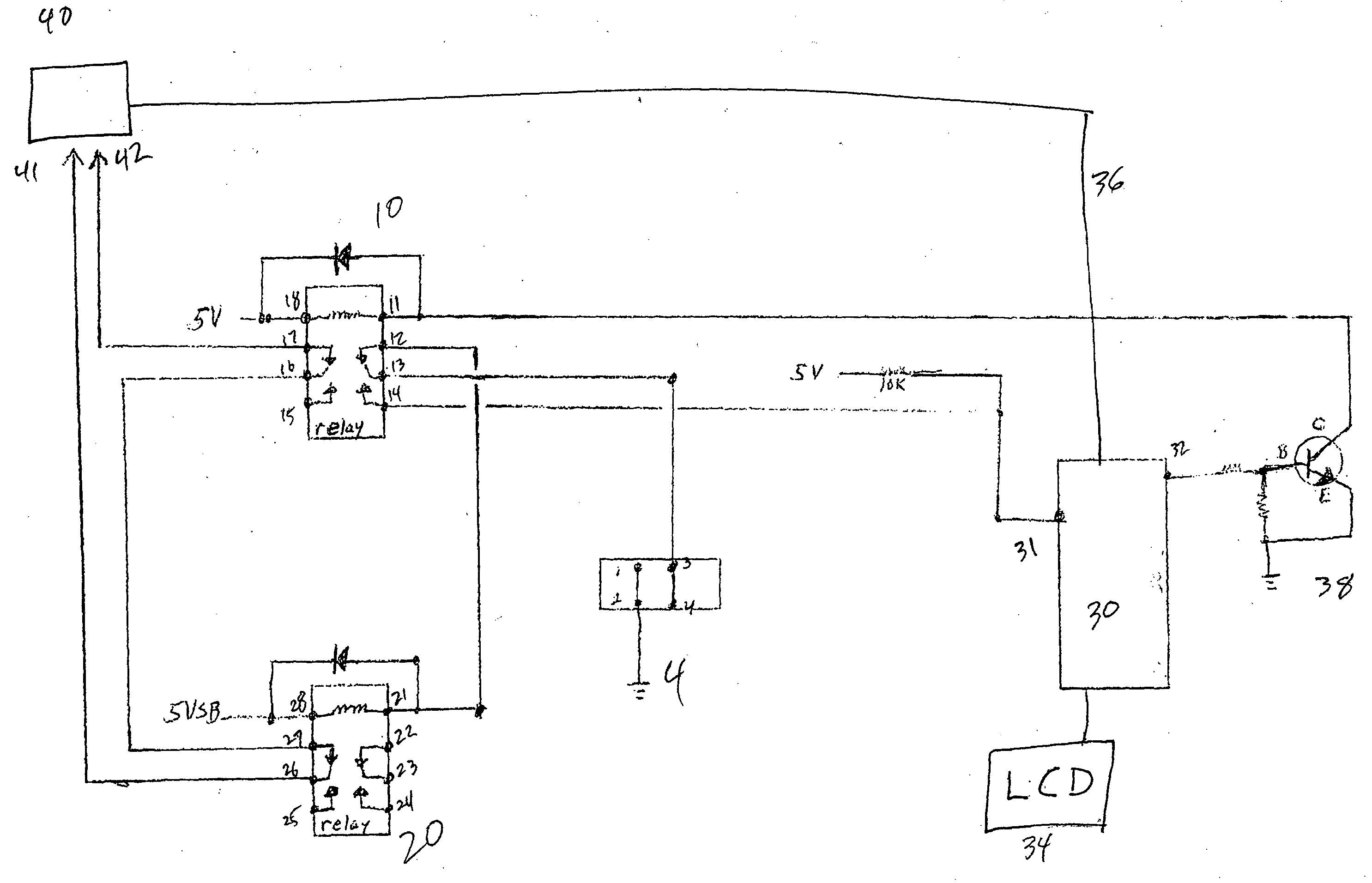
[0021] Referring now to the drawings in which like reference numerals refer to like components, FIG. 1 is a circuit diagram for the apparatus of the present invention. A main or primary circuit board 40 commonly referred to as a “motherboard” will be powered on and powered off by the push button in its cooperating circuitry with the other components of the present invention. It is a typical feature in most motherboards to control a power supply. The control generally maintains the power supply in a non-generating state when the overall device and motherboard are off. A certain voltage, +5 in the depicted embodiment, is maintained when the unit is off as a standby power source.

[0022] A first relay 10 serves as a control relay. A second relay 20 serves as a power relay. Solid state components may be substituted for the relays described herein without departing from the scope of the present invention. Those of skill in the art will recognize that the functionality of solid state compo...


PUM


Abstract

A protected dual purpose power / enter switch for an integrated receiver / decoder has a first relay and a second relay adapted for operative communication with a motherboard and with each other. A switch and a processor are in operative communication with the first relay. When the device is off, said switch is configured to activate the first and second relay to power up the device, and when said device is on, the first relay connects the switch to the processor as an enter switch. The switch may power off said device by entering a power off menu item displayed by said processor.

Description

CROSS-REFERENCE TO RELATED APPLICATIONS [0001] None. STATEMENT REGARDING FEDERALLY SPONSORED RESEARCH OR DEVELOPMENT [0002] Not Applicable. APPENDIX [0003] Not Applicable. BACKGROUND OF THE INVENTION [0004] 1. Field of the Invention [0005] The present invention is in the field of receivers and decoders for broadcast transmissions of data such as audiovisual data. [0006] 2. Related Art [0007] Hardware for the receipt of data transmissions such as audio and video increasingly receive the data in higher volumes and at faster speeds. This is particularly true of broadcast transmissions of audio and video data such as that transmitted according to MPEG protocols, and by streaming audio and video. Accordingly, the consequences of any inadvertent power shut down and resulting interruption of service becomes increasingly burdensome. The detrimental effect of such an interruption in services multiplies when the receiver / decoder equipment in question serves multiple end users, as for example,...

Claims


Application Information

Patent Timeline
IPC IPC(8): H01H9/00H04N
CPCH04N21/4436
Inventor PELKEY, GARY L.WILLIAMS, STANLEY L.
Owner NYTELL SOFTWARE LLC
Why Eureka
Try Eureka