
Ceramic ball bearing fracture test method

a technology of ceramic ball bearings and fracture test methods, which is applied in the field of material fracture testing, can solve the problems of low fracture toughness, easy cracking of ceramic balls, and significant drawbacks of ceramic balls

Active Publication Date: 2005-03-31
THE AEROSPACE CORPORATION
View PDF2 Cites 16 Cited by
  • Summary
  • Abstract
  • Description
  • Claims
  • Application Information

AI Technical Summary

Benefits of technology

[0016] The present invention is directed to a mechanical test method for directly measuring the fracture toughness of brittle balls such as ceramic and steel ball bearings. For example, the mechanical test method can be used to directly measure the fracture toughness of the silicon-nitride balls used in hybrid bearings. Using this test method, a starter crack is first placed in th ball at an equatorial position on the surface of the ball. Th ball is then placed betw en opposing platens that have hemispher

Problems solved by technology

Ceramic balls have significant drawbacks and limitations.
Therefore, under applied tension, the balls are prone to crack either at a preexisting manufacturing flaw or at a flaw that develops during service and usage.
Second, the preexisting flaws are eliminated, which ameliorates the low fracture toughness.
Unfortunately, these tests all use a rectilinear or cylindrical specimen that typically has a largest linear dimension that is on the order of several centimeters.
In contrast, ceramic balls used in even the largest capacity hybrid bearings have a diameter of much less than 1.5 cm, which makes it virtually impossible to fabricate specimens for any of these standard fracture tests due to the spherical shape of the balls and the limited volume of the balls.
At a sufficiently high applied indentation load, cracks can grow from the corners of the indentation as the indentation is loaded.
The indentation test is, however, not rigorously quantitative.
Disadvantageously, there is no current known test that can independently measure the fracture toughness of the ceramic balls.
The existing fracture toughness test methods are disadvantageously indirect and imprecise because these test methods rely upon a semiquantitative estimate of residual stress.
Disadvantageously, the existing test methods that directly measure the fracture toughness have only been applied to rectilinear specimens.

Method used


Image

  • Ceramic ball bearing fracture test method
  • Ceramic ball bearing fracture test method
  • Ceramic ball bearing fracture test method

Examples


Embodiment Construction

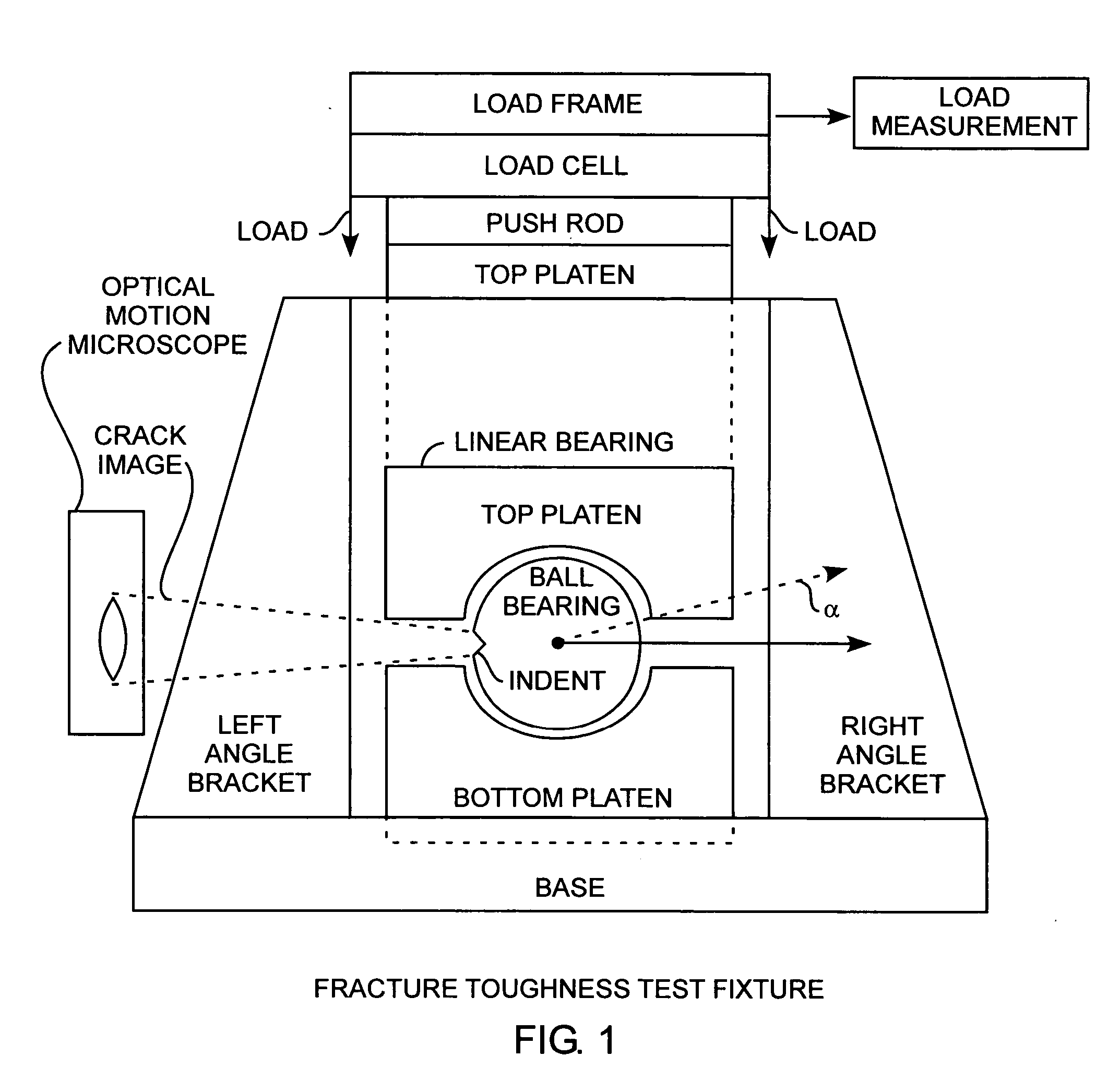
[0024] An embodiment of the invention is described with reference to the figures using reference designations as shown in the figures. Referring to FIG. 1, the mechanical test method can be implemented using a fracture toughness text fixture for directly measuring the fracture toughness of ceramic balls, such as are used in modern hybrid bearings. In practicing the method, a starter crack is first placed in the ball prior to the ball being placed in the test fixture. The ball is placed between opposing platens that have hemispherical sockets with radii equal to the radius of the ball radius. However, the depth of the hemispherical sockets is less than the radius of the ball. That is, the sockets of the lateens have a radial arc length that is less than a complete hemisphere such that the conforming arc length is less than ninety degrees from the north pole for the top platen and equally less than ninety degrees for the south pole, so that the midspan or equator of the ball does not ...


PUM


Abstract

A mechanical test method prescribes compressing brittle balls in spherical conforming opposing platens producing equatorial bulging, tensile stresses, and resulting indentation crack growth that is imaged for providing direct measurement of the fracture toughness of brittle balls, such as, silicon-nitride balls used in hybrid bearings as well as conventional steel ball bearings, with measurement errors being immune to characterizing the dimensions and positioning of the precrack indentations, so that, the test method is accurate, repeatable, and robust.

Description

FIELD F THE INVENTION [0001] The invention relates to the field of materials fracture testing. More particularly, the present invention relates to ceramic and metallic ball bearing fracture testing for manufacturing and qualifying high quality brittle ball bearings. BACKGROUND OF THE INVENTION [0002] Over th last decade, silicon-nitride Si3N4 balls have become an important component of advanced bearings used in a wide range of applications. The greatest commercial success for Si3N4 balls has been their use in hybrid bearings that combine the ceramic balls with steel races and that are known as silicon-nitride hybrid bearings. Compared to the steel balls, which the silicon-nitride balls replace, the ceramic balls are harder and less dense and offer higher compressive strength, better corrosion resistance, elevated operating temperature, and reduced lubrication requirements. These benefits make the hybrid bearings ideal for severe high-speed applications such as machine tool spindles,...

Claims


Application Information

Patent Timeline
IPC IPC(8): G01N3/00G01N3/02G01N3/06G01N3/08
CPCG01M13/04G01N3/08G01N2203/0647G01N2203/0066G01N2203/0276G01N2203/006
Inventor O'BRIEN, MICHAEL JAMESNELSON, BENJAMIN ALLEN
Owner THE AEROSPACE CORPORATION
Learn More