Wire, method of manufacturing the wire, and electromagnet using the wire

Inactive Publication Date: 2005-03-24
FUJIFILM BUSINESS INNOVATION CORP
View PDF3 Cites 30 Cited by
  • Summary
  • Abstract
  • Description
  • Claims
  • Application Information

AI Technical Summary

Benefits of technology

Therefore, the present invention is intended to solve the above problems in the prior art. More specifically, an object of the present invention is to provide a wire and an electromagnet which can effectively utilize characteristics of a carbon nanotube structure.
As the functional group specifically used for the condensation reaction, —COOH is particularly preferably used. Introduction of a carboxyl group to carbon nanotubes is relatively easy. Moreover, the resultant substance (carbon nanotube carboxylic acid) is highly reactive. Therefore, introduction of functional groups for forming a mesh structure to multiple places of one carbon nanotube is easy. In addition, the functional group easily reacts in a condensation reaction, thus being suitable for a formation of the carbon nanotube structure.

Problems solved by technology

Therefore, the carbon nanotubes are unable to exert sufficient performance.
In this case, however, the amount of binders decreases to result in reduced mechanical strength of a cable itself.
Thus, characteristics of the carbon nanotube itself resulting from a graphene sheet structure such as electric conductivity and mechanical strength can not be sufficiently exerted.

Method used


Image

  • Wire, method of manufacturing the wire, and electromagnet using the wire
  • Wire, method of manufacturing the wire, and electromagnet using the wire
  • Wire, method of manufacturing the wire, and electromagnet using the wire

Examples


example 1

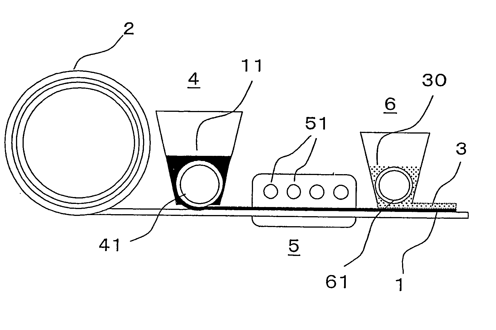
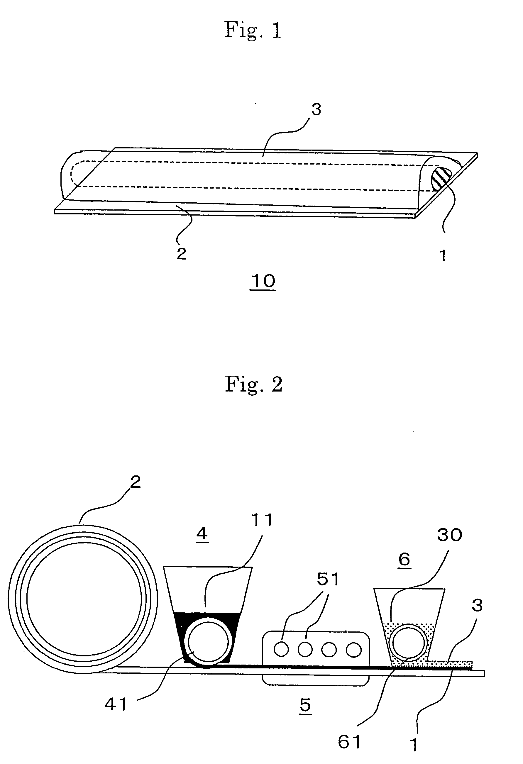
A wire was manufactured through a flow of a manufacturing method for a wire shown in FIG. 1. It should be noted that reference numerals in FIG. 1 may be used in the description of this example.

(A) Applying Step

(A-1) Preparation of Cross-Linking Application Liquid (Addition Step)

(1) Addition of Carboxyl Group . . . Synthesis of Carbon Nanotube Carboxylic Acid

30 mg of multi-layer carbon nanotube powder (purity: 90%, average diameter: 30 nm, average length: 3 μm, available from Science Laboratory Inc.) was added to 20 ml of concentrated nitric acid (a 60 mass % aqueous solution, available from KANTO KAGAKU) for reflux at 120° C. for 20 hours to synthesize carbon nanotube carboxylic acid. A reaction scheme of the above is shown in FIG. 4. In FIG. 4, a carbon nanotube (CNT) is represented by two parallel lines (same applies for other figures relating to reaction scheme).

The temperature of the liquid solution was returned to room temperature and centrifuged at 5,000 rpm for 15 ...

verification experiment

(Verification Experiment)

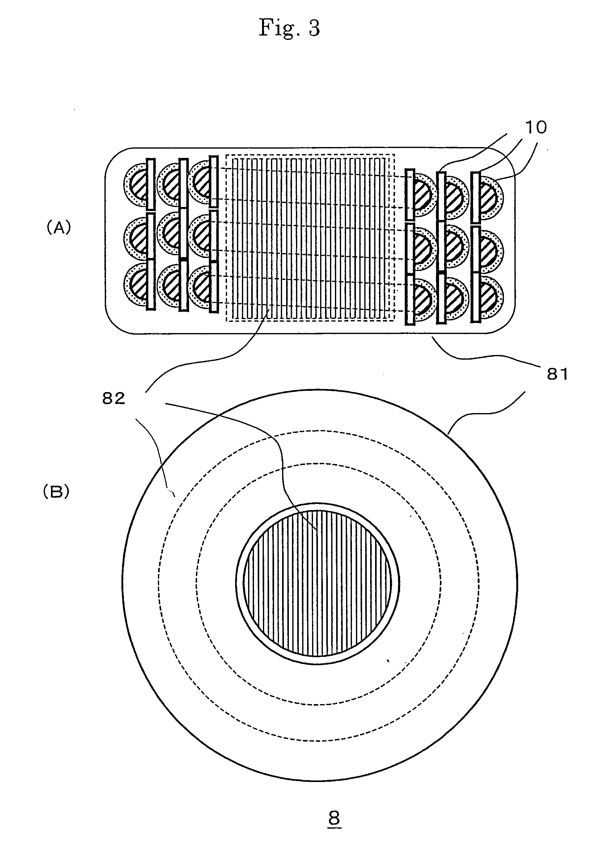
The current-voltage measurement of the wire obtained in Example 1 was performed to confirm that a current with a current density of 4×10⁴ A / cm2 flowed (FIG. 7). The value is comparable to four times a critical current density of a superconductor (in general of the order of 10,000 A / cm2). An electromagnet was fabricated by using the wire. The wire was wound about an iron cylinder 82 with a diameter of 3 cm and a length of 10 cm at 50 turns / 10 cm to fabricate an electromagnet. A current of 0.1 A was passed through the wire, and the magnetic field strength directly above the electromagnet was measured with a gaussmeter to confirm that a magnetic field with a magnetic field strength H of 160 A / m was generated.

As described above, according to the present invention, the wire which is excellent in electric conductivity or mechanical properties and in which bonding between carbon nanotubes is established with reliability is obtained, so that characteristics of th...


PUM


Abstract

To provide a wire excellent in electrical characteristics or in mechanical characteristics. A wire is constructed at least by a carbon nanotube structure layer (1) in which plural carbon nanotubes mutually cross-link to configure a mesh structure on the surface of a substrate (2). A method of manufacturing the wire includes: an applying step of applying to the surface of the substrate (2) a liquid solution containing a carbon nanotube having a functional group; and a step of curing the liquid solution after the application. An electromagnet scarcely causing a loss is formed using the wire.

Description

FIELD OF THE INVENTION AND RELATED ART STATEMENT The present invention relates to a wire using a carbon nanotube structure, a method of manufacturing the wire, and an electromagnet using the wire. Carbon nanotubes (CNTs), with their unique shape and characteristics, are being considered for various applications. Carbon nanotubes have a tubular shape of one-dimensional nature which is obtained by rolling one or more graphene sheets composed of six-membered rings of carbon atoms into a tube. Those that are formed from one graphene sheet are called single-wall nanotubes (SWNTs) while those that are formed from graphene sheet layers are called multi-wall nanotubes (MWNTs). SWNTs are about 1 nm in diameter whereas multi-wall carbon nanotubes measure several tens nm in diameter, and both are far thinner than their predecessors, which are called carbon fibers. One of the characteristics of carbon nanotubes is that the aspect ratio of length to diameter is very large since the length of ...

Claims


Application Information

Patent Timeline
IPC IPC(8): B82B1/00B05D5/12B05D7/24B82B3/00C01B31/02H01B1/00H01B1/04H01B1/24H01B5/02H01B7/00H01B13/00H01F7/06H01L21/8238
CPCB82Y10/00H01F7/202H01B1/04B82Y30/00
Inventor MANABE, CHIKARAANAZAWA, KAZUNORIHIRAKATA, MASAKIKISHI, KENTAROSHIGEMATSU, TAISHIWATANABE, MIHOISOZAKI, TAKASHIWATANABE, HIROYUKIOOMA, SHIGEKIOKADA, SHINSUKE
Owner FUJIFILM BUSINESS INNOVATION CORP
Why Eureka
Try Eureka