
Synchronization in a broadcast OFDM system using time division multiplexed pilots

a technology of time division and multiplexing, applied in the field of data communication, can solve the problem that the receiver also consumes resources to perform synchronization, and achieve the effect of more accurate channel estimation

Inactive Publication Date: 2005-03-24
QUALCOMM INC
View PDF20 Cites 271 Cited by
  • Summary
  • Abstract
  • Description
  • Claims
  • Application Information

AI Technical Summary

Benefits of technology

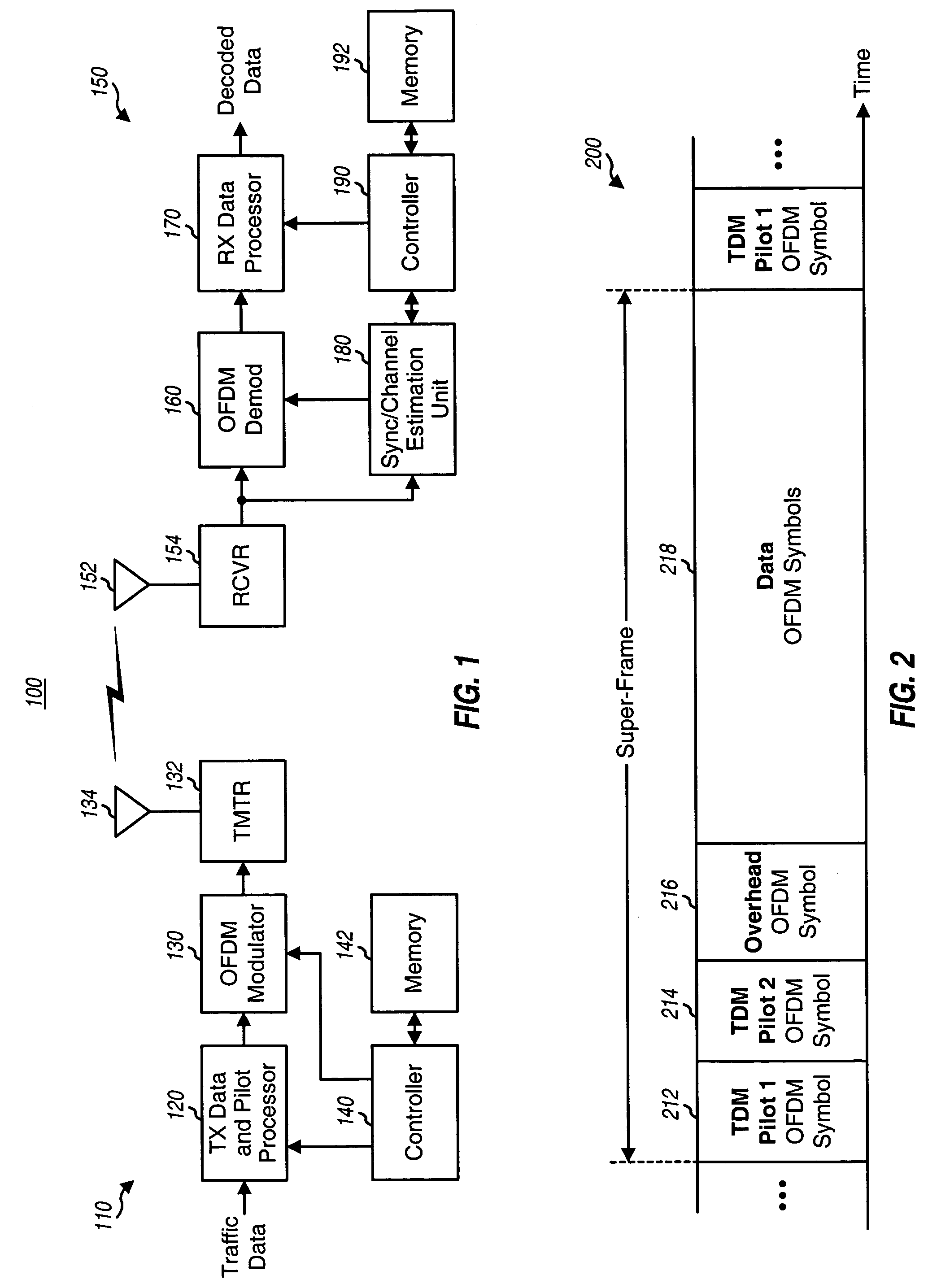
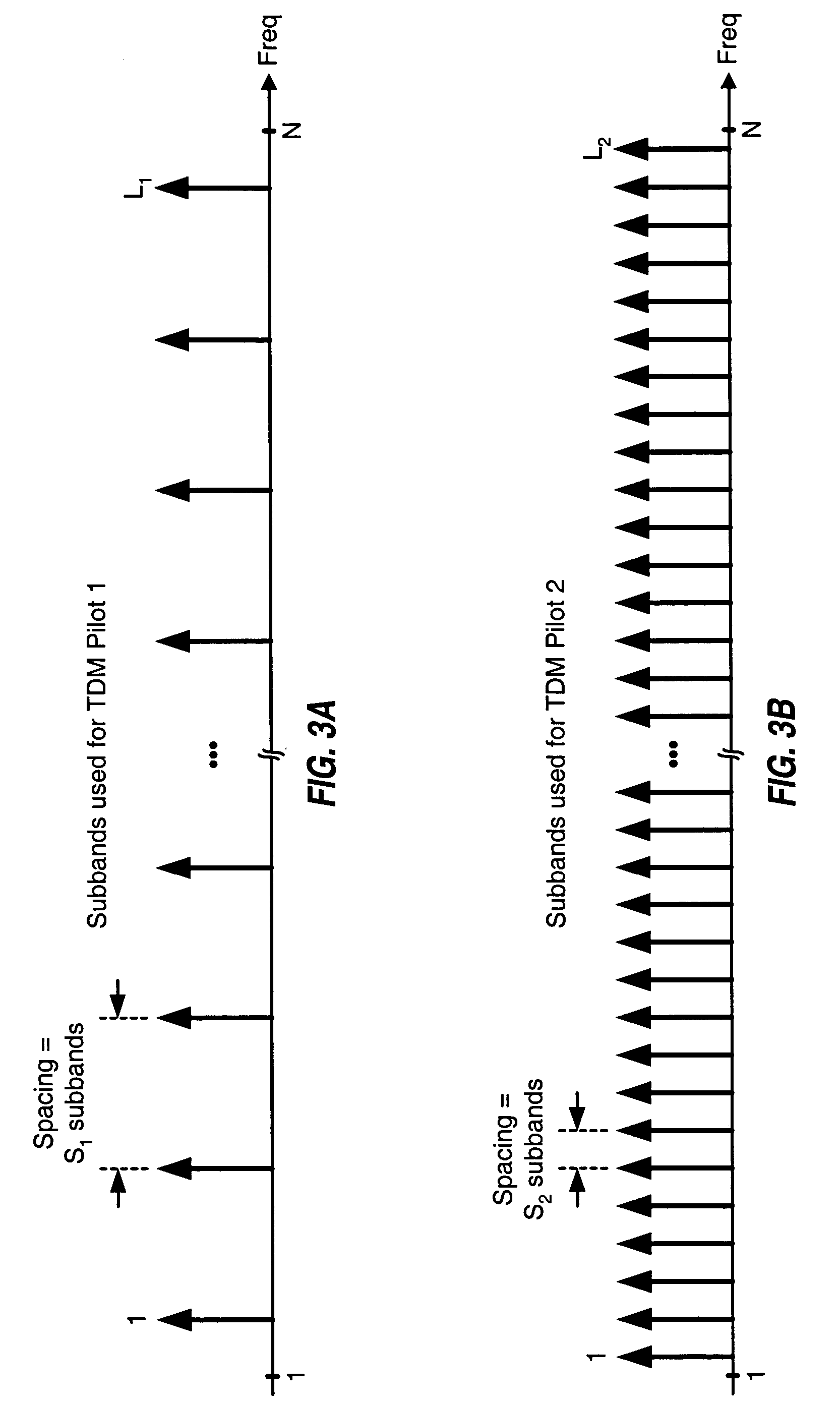
A receiver can perform synchronization based on the first and second TDM pilots. The receiver can process the first TDM pilot to obtain frame timing and frequency error estimate. The receiver may compute a detection metric based on a delayed correlation between different pilot-1 sequences for the first TDM pilot, compare the detection metric against a threshold, and declare detection of the first TDM pilot (and thus a frame) based on the comparison result. The receiver can also obtain an estimate of the frequency error in the received OFDM symbol based on the pilot-1 sequences. The receiver can process the second TDM pilot to obtain symbol timing and a channel estimate. The receiver may derive a channel impulse response estimate based on a received OFDM symbol for the second TDM pilot, detect the start of the channel impulse response estimate (e.g., based on the energy of the channel taps for the channel impulse response), and derive the symbol timing based on the detected start of the channel impulse response estimate. The receiver may also derive a channel frequency response estimate for the N total subbands based on the channel impulse response estimate. The receiver may use the first and second TDM pilots for initial synchronization and may use the FDM pilot for frequency and time tracking and for more accurate channel estimation.

Problems solved by technology

The transmitter typically expends system resources to support synchronization, and the receiver also consumes resources to perform synchronization.

Method used


Image

  • Synchronization in a broadcast OFDM system using time division multiplexed pilots
  • Synchronization in a broadcast OFDM system using time division multiplexed pilots
  • Synchronization in a broadcast OFDM system using time division multiplexed pilots

Examples


Embodiment Construction

The word “exemplary” is used herein to mean “serving as an example, instance, or illustration.” Any embodiment or design described herein as “exemplary” is not necessarily to be construed as preferred or advantageous over other embodiments or designs.

The synchronization techniques described herein may be used for various multi-carrier systems and for the downlink as well as the uplink. The downlink (or forward link) refers to the communication link from the base stations to the wireless devices, and the uplink (or reverse link) refers to the communication link from the wireless devices to the base stations. For clarity, these techniques are described below for the downlink in an OFDM system.

FIG. 1 shows a block diagram of a base station 110 and a wireless device 150 in an OFDM system 100. Base station 110 is generally a fixed station and may also be referred to as a base transceiver system (BTS), an access point, or some other terminology. Wireless device 150 may be fixed or mob...


PUM


Abstract

In an OFDM system, a transmitter broadcasts a first TDM pilot on a first set of subbands followed by a second TDM pilot on a second set of subbands in each frame. The subbands in each set are selected from among N total subbands such that (1) an OFDM symbol for the first TDM pilot contains at least S1 identical pilot-1 sequences of length L1 and (2) an OFDM symbol for the second TDM pilot contains at least S2 identical pilot-2 sequences of length L2, where L2>L1, S1·L1=N, and S2·L2=N. The transmitter may also broadcast an FDM pilot. A receiver processes the first TDM pilot to obtain frame timing (e.g., by performing correlation between different pilot-1 sequences) and further processes the second TDM pilot to obtain symbol timing (e.g., by detecting for the start of a channel impulse response estimate derived from the second TDM pilot).

Description

BACKGROUND I. Field The present invention relates generally to data communication, and more specifically to synchronization in a wireless broadcast system using orthogonal frequency division multiplexing (OFDM). II. Background OFDM is a multi-carrier modulation technique that effectively partitions the overall system bandwidth into multiple (N) orthogonal frequency subbands. These subbands are also referred to as tones, sub-carriers, bins, and frequency channels. With OFDM, each subband is associated with a respective sub-carrier that may be modulated with data. In an OFDM system, a transmitter processes data to obtain modulation symbols, and further performs OFDM modulation on the modulation symbols to generate OFDM symbols, as described below. The transmitter then conditions and transmits the OFDM symbols via a communication channel. The OFDM system may use a transmission structure whereby data is transmitted in frames, with each frame having a particular time duration. Diffe...

Claims


Application Information

Patent Timeline
IPC IPC(8): H04B3/10H04JH04J1/16H04J11/00
CPCH04L5/005H04L25/022H04L27/2613H04L2027/003H04L27/2662H04L27/2665H04L27/2657H04L27/26134H04B1/76H04L27/26
Inventor LING, FUYUNGUPTA, ALOK KUMARKRISHNAMOORTHI, RAGHURAMANMURALI, RAMASWAMYVIJAYAN, RAJIVVRCELJ, BOJAN
Owner QUALCOMM INC
Learn More