
Modifying gray voltage signals in a display device

a display device and gray voltage technology, applied in the field of display devices, can solve the problems of liquid crystal capacitors that may take a longer time than desired to reach the target voltage, liquid crystal capacitors that cannot respond quickly to the applied electric field, and special effects of flickering phenomenon

Active Publication Date: 2005-03-24
SAMSUNG DISPLAY CO LTD
View PDF3 Cites 31 Cited by
  • Summary
  • Abstract
  • Description
  • Claims
  • Application Information

AI Technical Summary

Benefits of technology

In one aspect, the invention is a method of driving a display device by determining a first difference Δ1, wherein Δ1 is a difference between gray signals of two consecutive frames, comparing Al to a predetermined value to obtain a comparison result, and using the comparison result to determine a modified current gray signal. The modified current gray signal is applied to a current frame to improve image quality.
In yet another aspect, the invention is a display device with improved image quality. The display device includes a display panel having pixels defined by gate lines and data lines and a driving apparatus for providing signals to the gate lines and the data lines. The driving apparatus includes a frame memory, a lookup table, a signal comparator, and a calculator. The frame memory, which is configured to receive gray voltages, stores the gray voltage levels for a plurality of frames. The lookup table, which is coupled to the frame memory, stores modification factors. The signal comparator, which compares the gray voltage from the frame memory and selects a modification factor from the modification factors based on the comparison. The calculator receives the modification factor and determines a modified current gray signal by using the selected modification factor.

Problems solved by technology

Currently, the liquid crystal molecules do not respond to the applied electric field fast enough to display clean fast-moving images.
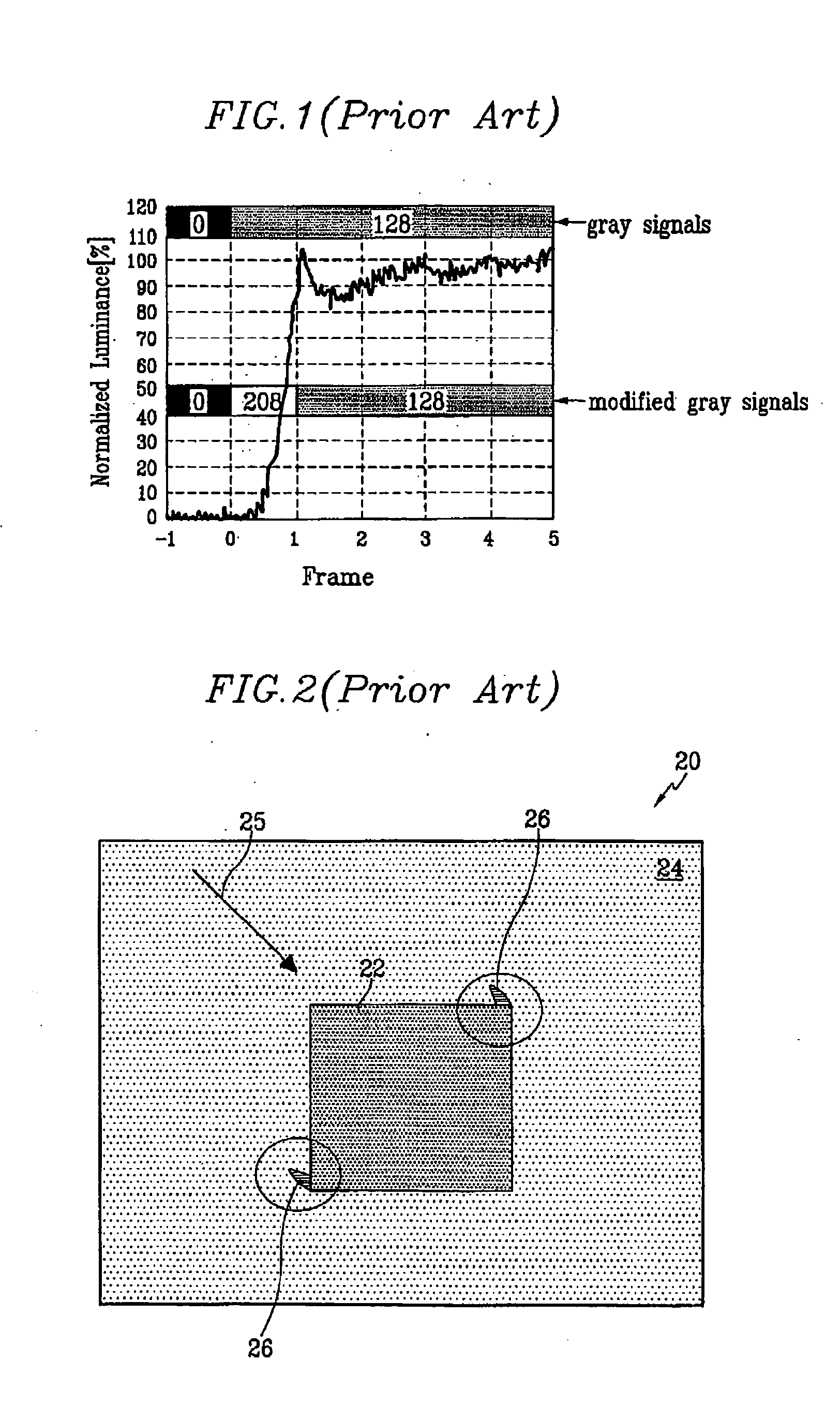
When the difference between the target voltage and the previous voltage is large, the liquid crystal capacitor may take a longer than desired length of time to reach the target voltage.
The “flickering” phenomenon is especially bad where gray level voltages are low.
The undesirable appearance of cyan-colored artifacts 26 indicates that DCC-based modification does not always provide the desired result.
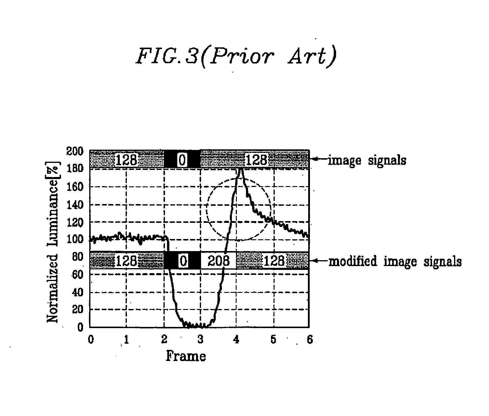
Thus, in cases like above where the “0” signal is sustained only for a brief moment (i.e., one frame) and not stabilized, applying the signal 208 results in overshooting.

Method used


Image

  • Modifying gray voltage signals in a display device
  • Modifying gray voltage signals in a display device
  • Modifying gray voltage signals in a display device

Examples


example 1

A combination of three gray voltage levels is classified into the first class if the gray voltage level does not change much between the first frame and the second frame, but changes significantly between the second frame and the third frame. As used herein, the first frame is the previous frame, the second frame is the current frame, and the third frame is the next frame that will follow the current frame. A modification factor is determined according to the values of the current gray signal gn and the next gray signal gn+1, and applied to the current frame. More specifically, a modified current gray signal that is applied to the current frame is determined anticipating the large change in the gray voltage level that is about to take place. Effectively, a part of the upcoming change in the gray voltage is applied to the current frame in what is herein referred to as “pre-shooting.” In this case, the modified current gray signal is about equal to the preliminary modified signal g′1...

example 2

This example illustrates an embodiment of the invention where a combination of three gray voltage levels are placed into one of five possible classes.

A combination is placed into the first class if the difference between the previous gray signal gn−1 and the current gray signal gn is less than the first predetermined value (x and the next gray signal gn+1 is greater than the current gray signal gn.

In the second class, the previous gray signal gn−1 is larger than the sum of the current gray signal gn and the first predetermined value α, and the difference between the current gray signal gn and the next gray signal gn+1 is greater than the second predetermined value β.

In the third class, the previous gray signal gn−1 is greater than a sum of the current gray signal gn and the first predetermined value α, and the difference between the current gray signal gn and the next gray signal gn+1 is les than the second predetermined value β.

In the fourth class, the current gray signal ...

example 3

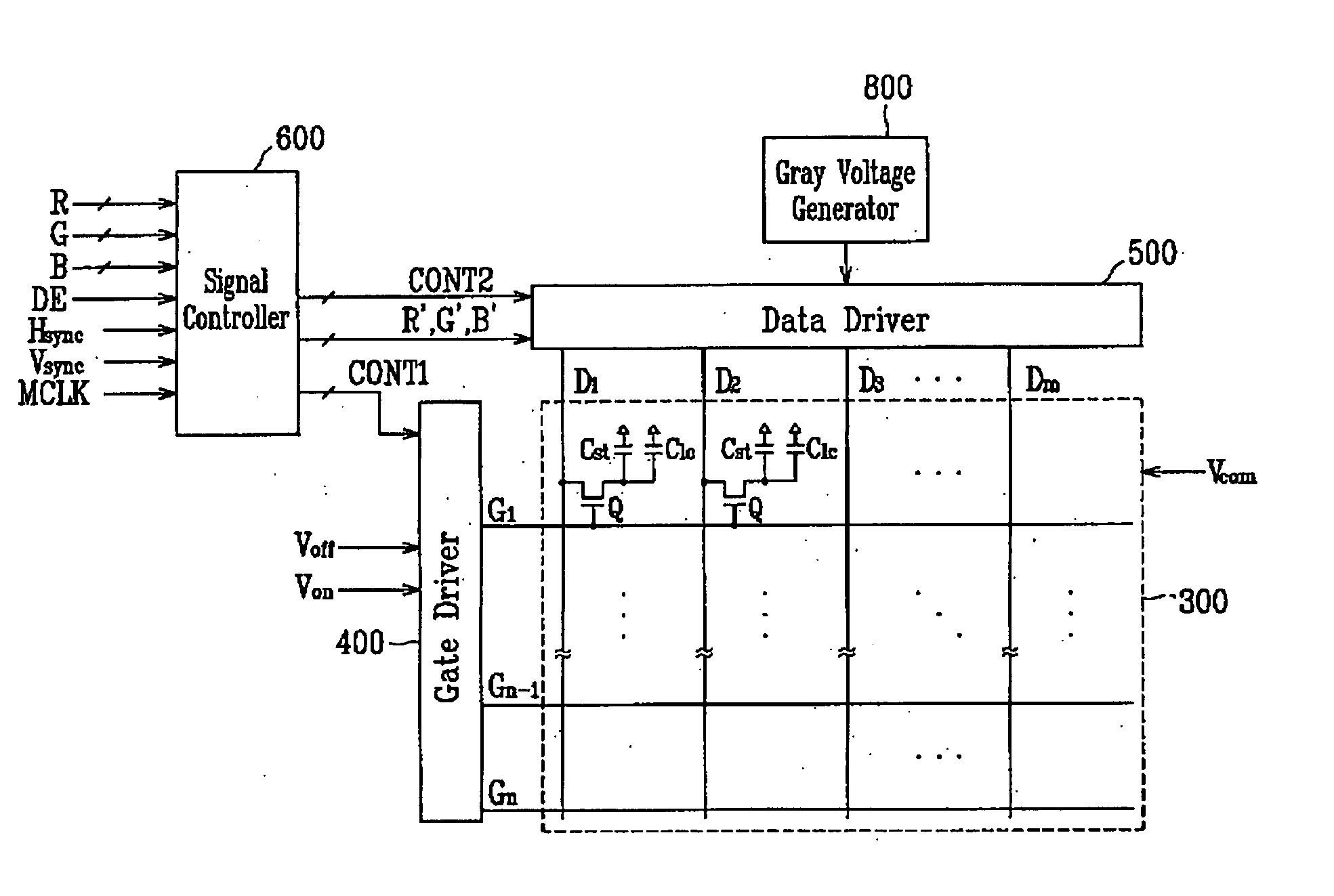
FIG. 7 is a block diagram of a first embodiment of the gray voltage modification module 650 for implementing the above-describe method. As shown in FIG. 7, the modification module 650 includes a signal receiver 61, a frame memory 62 coupled to the signal receiver 61, and a gray signal converter 64 that is coupled to both the signal receiver 61 and the frame memory 62.

The gray signal converter 64 includes a lookup table (LUT) 640, a calculator 643, and a signal comparator 644. The lookup table (LUT) 640 is coupled to the signal receiver 61 and the frame memory 62. More specifically, the input to the gray signal converter 64 is coupled to the lookup table 640, which receives input from the signal receiver 61 and the frame memory 62. The output of the gray signal converter 64 is coupled to a calculator 643.

The signal receiver 61 receives a raw input signal for the next frame (In+,) and converts it to a gray voltage signal that can be processed by the modification module 650. The si...


PUM

PropertyMeasurementUnit
current grayaaaaaaaaaa
currentaaaaaaaaaa
voltagesaaaaaaaaaa

Abstract

A method and apparatus for driving a display device, as well as a display device incorporating such method and apparatus, are presented. The method includes determining a first difference Δ1, wherein Δ1 is a difference between gray signals of two consecutive frames, comparing Δ1 to a predetermined value to obtain a comparison result, and using the comparison result to determine a modified current gray signal. The modified current gray signal is applied to a current frame to improve image quality. In another aspect, the invention includes a method of driving a display device by determining the gray signal levels for a first frame, a second frame that follows the first frame, and a third frame. A modified current gray signal is determined based on the relative magnitudes of the three gray signal levels, and applied to the current frame.

Description

RELATED APPLICATIONS This application claims priority, under 35 USC § 119, from Korean Patent Application No. 2003-0055422 filed on Aug. 11, 2003 and Korean Patent Application No. 2004-0030426 filed on Apr. 30, 2004, both of which are incorporated by reference herein in its entirety. FIELD OF INVENTION The invention relates generally to display devices and particularly to controlling the gray voltage signals in display devices. BACKGROUND A liquid crystal display (LCD) includes a pair of panels with field generating electrodes and a liquid crystal layer with dielectric anisotropy disposed between the two panels. An electric field is formed in the liquid crystal layer by using the electrodes, and the desired images are generated by adjusting the electric field to control the light transmittance through the liquid crystal layer. The LCD devices include flat panel display (FPD) devices, which frequently come in the form of TFT-LCDs that use thin film transistors (TFTs) for pixel con...

Claims


Application Information

Patent Timeline
Patent Type & Authority Applications(United States)
IPC IPC(8): G09G3/20G02F1/133G09G3/36
CPCG09G3/3648G09G2340/16G09G2320/0252G09G2320/0247
Inventor LEE, SEUNG-WOOKIM, MOUNG-SU
Owner SAMSUNG DISPLAY CO LTD
Learn More