Pressure glow plug for a diesel engine
a technology for diesel engines and glow plugs, which is applied in the direction of machines/engines, lighting and heating apparatus, instruments, etc., can solve the problems of affecting the pressure sensor, affecting the output pressure, etc., and achieves the effects of reducing or optimizing emission values, increasing power, and consumption values
- Summary
- Abstract
- Description
- Claims
- Application Information
AI Technical Summary
Benefits of technology
Problems solved by technology
Method used
Image
Examples
first embodiment
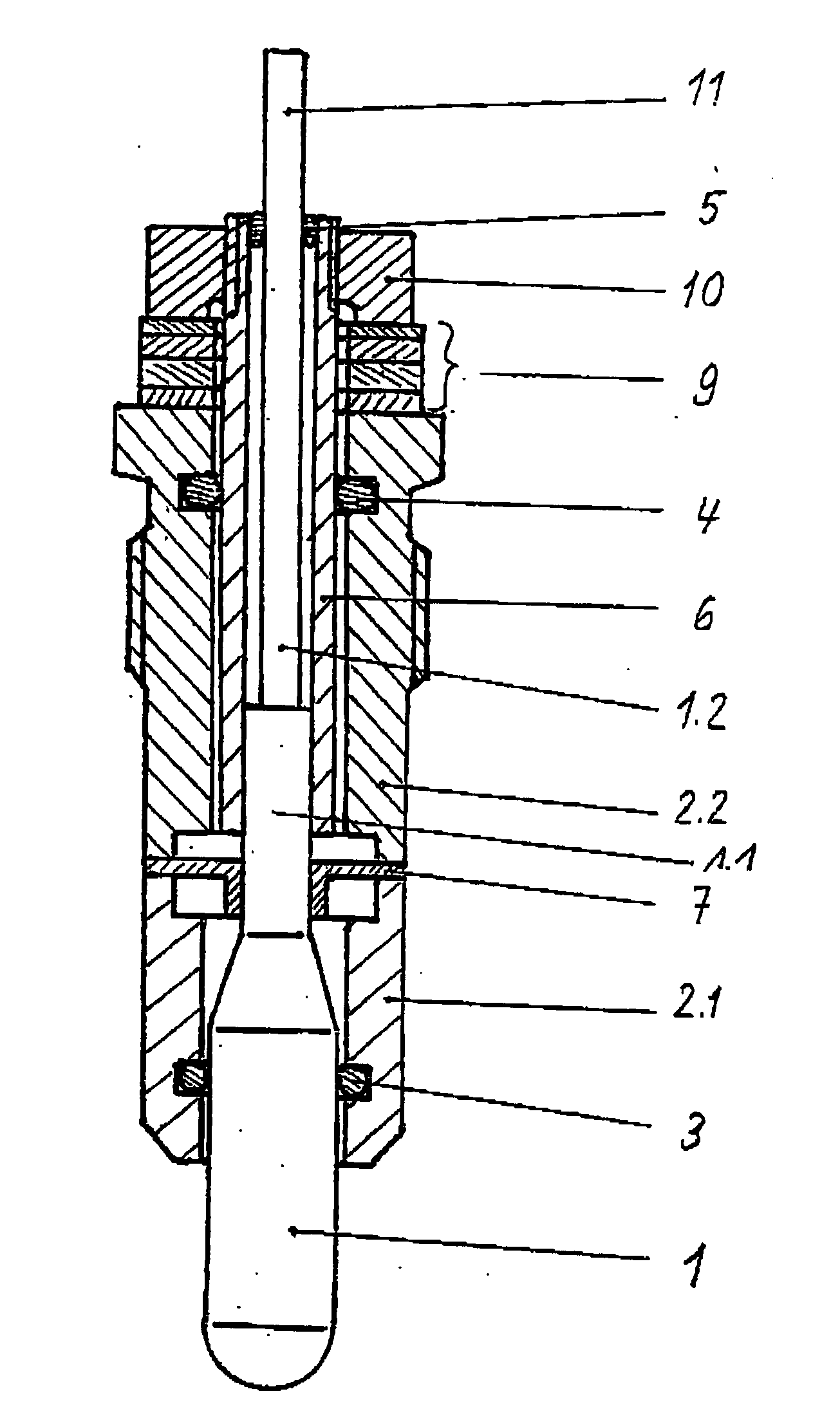
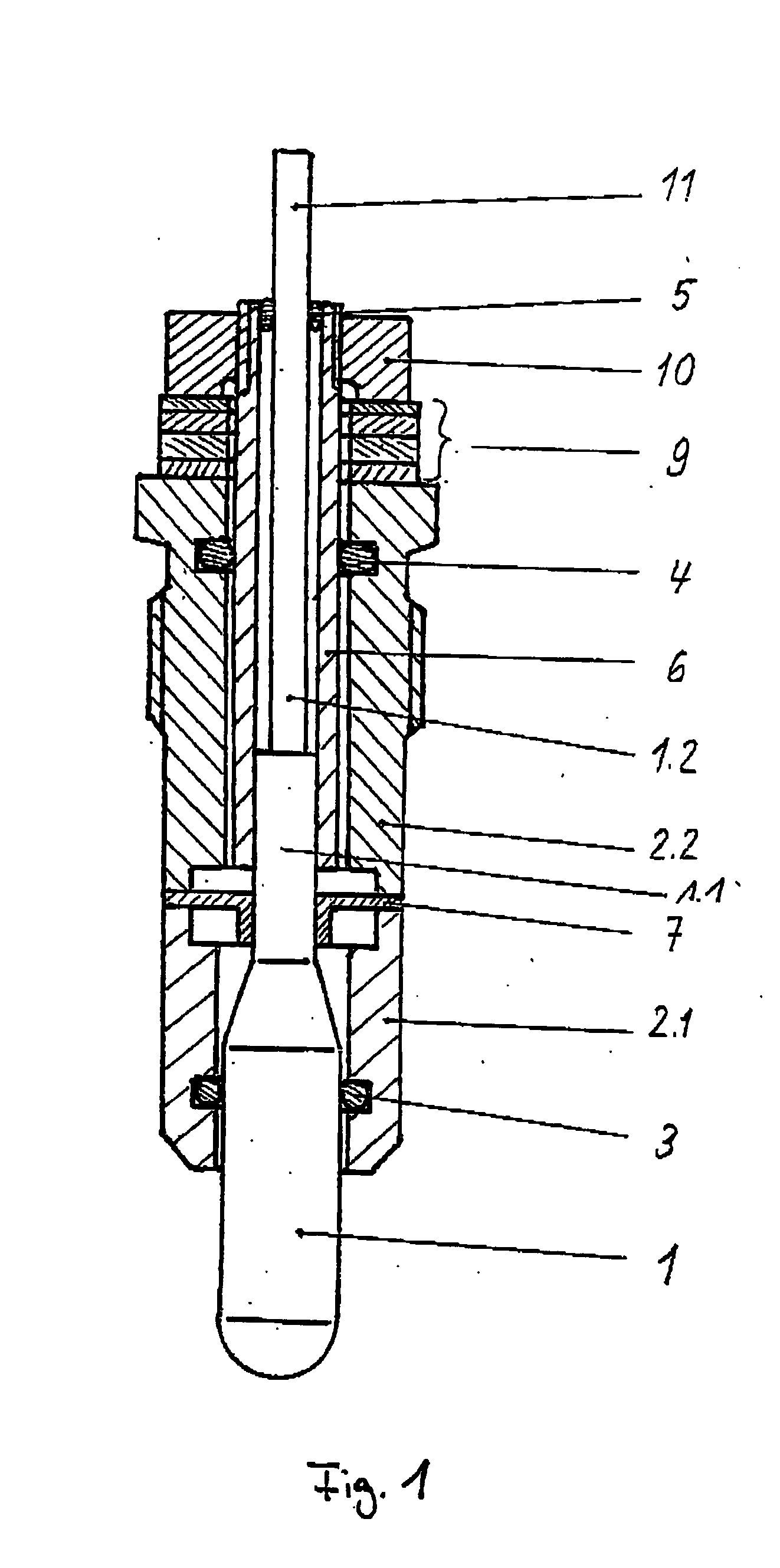
[0019] the pressure glow plug according to the invention that is illustrated in FIG. 1 comprises a heating rod 1 arranged in a glow plug body, wherein the glow plug body is composed of two parts, namely an upper part 2.2 on the connection endand a lower part 2.1 on the combustion chamber side. The heating rod 1 has a reduced diameter in the region of the connection end, and a membrane 7 is fixed to the heating rod 1 in this region. The membrane 7 is realized in such a way that it transmits the heat of the heating rod 1 to the glow plug body 2, ensures the ground connection required for the glow function of the pressure glow plug and seals the arrangement in a gas-tight fashion in the direction of the connection end of the glow plug. For this purpose, the membrane 7 is rigidly arranged on the end face of the upper body part 2.1, for example, by means of laser welding.
[0020] A contact tube 6 extends from the membrane 7 in the direction of the connection end of the glow plug, and the c...
second embodiment
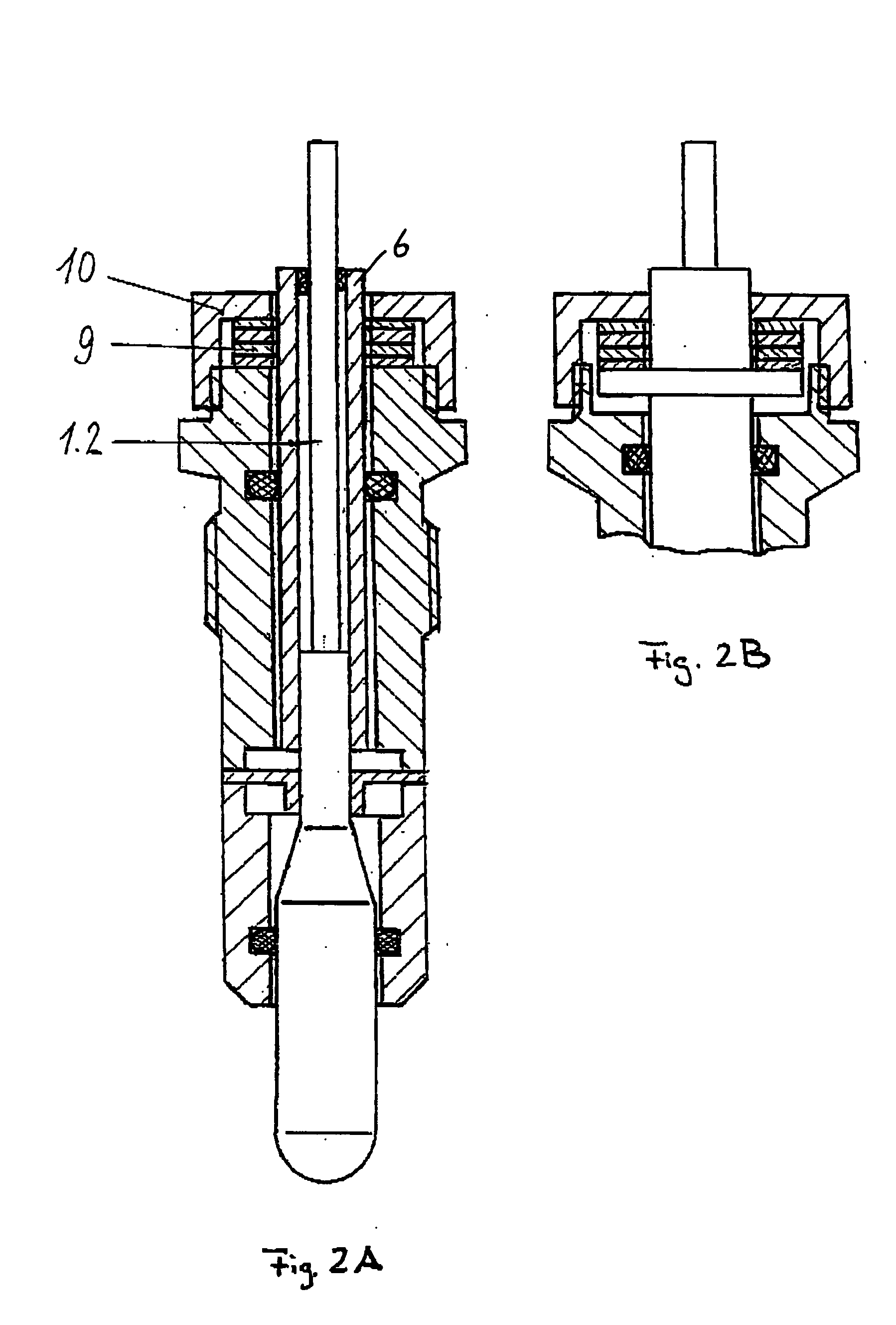
[0029]FIGS. 2A and 2B show two variations of the pressure glow plug according to the invention, wherein the second embodiment has the same basic design as the embodiment illustrated in FIG. 1.
[0030] In contrast to the embodiment illustrated in FIG. 1, the sensor arrangement 9 is supported in an insulated fashion on a shoulder of the contact tube 6 as shown in FIG. 2A or on a support ring that is fixed on the contact tube 6 as shown in FIG. 2B or directly on the end of the contact tube 6 that is braced relative to the upper part2.2 of the glow plug body by means of the tensioning element 10.
[0031] It is also possible to directly arrange the shoulder for supporting the sensor arrangement 9 or the corresponding support ring on the internal pole.
[0032] In this second embodiment, the cylinder pressure acting upon the heating rod 1 leads to an increase in the pressure acting upon the sensor arrangement 9 because the sensor arrangement 9 is more intensely pressed against the tensioning e...
third embodiment
[0033]FIGS. 3A and 3B show the pressure glow plug according to the invention, the basic design of which corresponds to that of the first two embodiments illustrated in FIGS. 1 and 2.
[0034] In the embodiment illustrated in FIG. 3A, a sensor element 8 that is realized, for example, in the form of a strain gauge, is arranged on a carrier element 9, for example, a bowl-type membrane, that has a defined flexibility in the axial direction, wherein the sensor element is directly fixed between the contact tube 6 and the upper part 2.2 of the glow plug body 2, for example, by means of welding.
[0035] In this embodiment, the movement of the heating rod 1, or its extension in the form of the contact tube 6, relative to the upper part 2.2 of the glow plug body leads to an elongation of the flexible carrier element 9 due to the increasing cylinder pressure. The resulting tensile stress or elongation of the sensor element 8 causes a signal change that can be detected and evaluated.
[0036] In the ...
PUM
 Abstract
Description
Claims
Application Information
 - R&D
- Intellectual Property
- Life Sciences
- Materials
- Tech Scout
- Unparalleled Data Quality
- Higher Quality Content
- 60% Fewer Hallucinations
Browse by: Latest US Patents, China's latest patents, Technical Efficacy Thesaurus, Application Domain, Technology Topic, Popular Technical Reports.
© 2025 PatSnap. All rights reserved.Legal|Privacy policy|Modern Slavery Act Transparency Statement|Sitemap|About US| Contact US: help@patsnap.com


