
Method and system for proactive drive replacement for high availability storage systems

Active Publication Date: 2005-03-17
COPAN SYST INC +1
View PDF49 Cites 69 Cited by
  • Summary
  • Abstract
  • Description
  • Claims
  • Application Information

AI Technical Summary

Benefits of technology

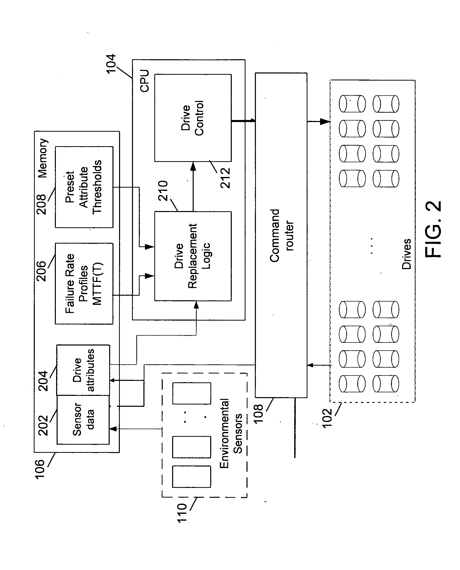
In accordance with an embodiment of the invention, the method for prevention of failure of disk drives uses factors such as reallocated sector count (RSC), read error rate (RSE), seek error rate (SKE), spin retry count (SRC), and the like. These factors can easily be obtained from disk drives through the Self-Monitoring, Analysis, and Reporting Technology (SMART) interface, which is a part of most currently available disk drives. Factors from environmental sensors can also be used to predict the failure of disk drives.

Problems solved by technology

An increase in the amount and complexity of these applications has resulted in a proportional increase in the demand for larger storage capacities.
However, large storage capacities demand reliable storage devices with reasonably high data transfer rates.
Moreover, the storage capacity of a single storage device cannot be increased beyond a certain limit.
However, such data redundancy schemes may be an overhead to the data storage system.
RAID storage systems suffer from inherent drawbacks that reduce their availability.
During reconstruction, the data on the failed drive is unavailable.
Further, if more than one disk drive fails, data on both drives cannot be reconstructed if there is single drive redundancy, typical of most RAID storage systems.
The probability of failure increases as the number of disk drives in a RAID storage system increases.
This reduces the probability of failure of large RAID systems.
Further, the use of smaller RAID systems also reduces the time it takes to reconstruct data on a spare disk drive in the event of a disk drive failure.
When a RAID system loses a critical number of disk drives, there is a period of vulnerability from the time the disk drives fail until the time data reconstruction on the spare drives completes.
During this time interval, the RAID system is exposed to the possibility of additional disk drives failing which would cause a catastrophic failure.
A catastrophic failure of a RAID system results in unrecoverable data loss.
In this method, failure is predicted with the help of error analysis.
In flyheight analysis, the failure is predicted if the flyheight of the read / write head above the disk head is too low.
If these factors exceed the thresholds, then failure is predicted.
However, the methods and systems described above suffer from one or more of the following shortcomings.
Further, the systems do not consider the sudden rise of these factors for predicting failure of disk drives.

Method used


Image

  • Method and system for proactive drive replacement for high availability storage systems
  • Method and system for proactive drive replacement for high availability storage systems
  • Method and system for proactive drive replacement for high availability storage systems

Examples


Embodiment Construction

Embodiments of the present invention provide a method, system and computer program product for preventing the failure of disk drives in high availability storage systems. Failure of disk drives is predicted and an indication for their replacement is given. Failure is predicted by the monitoring of factors, including those relating to the aging of disk drives, early onset of errors in disk drives and the acceleration of these factors.

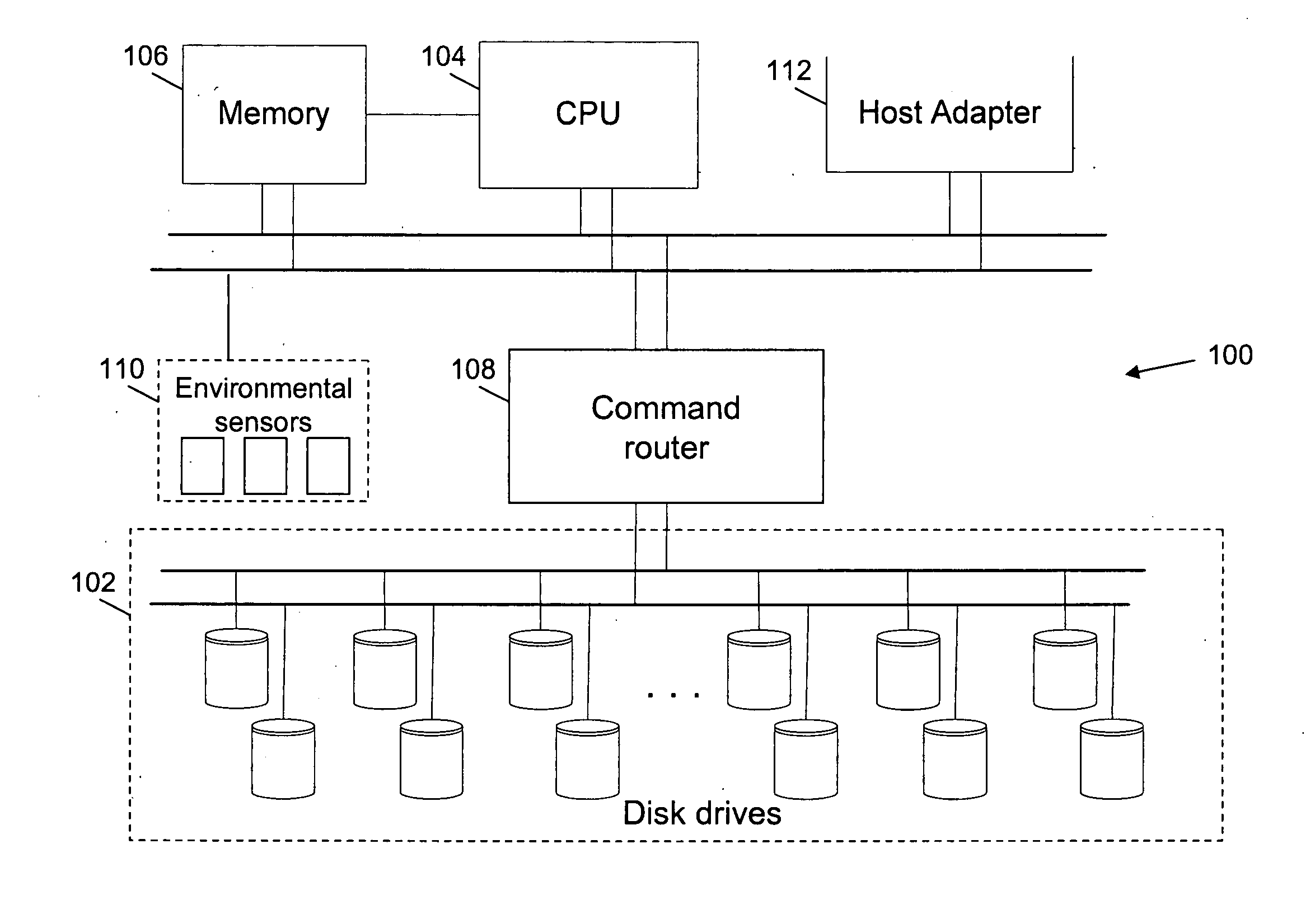
FIG. 1 is a block diagram illustrating a storage system 100 in accordance with an embodiment of the invention. Storage system 100 includes disk drives 102, a Central Processing Unit (CPU) 104, a memory 106, a command router 108, environmental sensors 110 and a host adaptor 112. Storage system 100 stores data in disk drives 102. Further, disk drives 102 store parity information that is used to reconstruct data in case of disk drive failure. CPU 104 controls storage system 100. Among other operations, CPU 104 calculates parity for data stored in disk dri...


PUM


Abstract

Methods for preventing the failure of disk drives in storage systems are disclosed. A system and a computer program product for preventing the failure are also disclosed. Factors relating to the aging or early onset of errors in a disk drive are monitored. These factors are then compared to thresholds. In case the thresholds are exceeded, an indication for the replacement of the disk drive is given. Sudden rises in the factors are also used to indicate the impeding failure of disk drives.

Description

BACKGROUND The present invention relates generally to digital processing systems. More specifically, the present invention relates to a method of prevention of failures of disk drives in high availability storage systems. Typically, in computing applications, data storage systems include storage devices such as hard disk drives, floppy drives, tape drives, compact disks, and the like. An increase in the amount and complexity of these applications has resulted in a proportional increase in the demand for larger storage capacities. Consequently, the production of high capacity storage devices has increased in the past few years. However, large storage capacities demand reliable storage devices with reasonably high data transfer rates. Moreover, the storage capacity of a single storage device cannot be increased beyond a certain limit. Hence, various data storage system configurations and topologies using multiple storage devices are commonly used to meet the growing demand for incre...

Claims


Application Information

Patent Timeline
IPC IPC(8): G06F11/00
CPCG06F11/008G11B19/04G06F11/2094G06F11/1662
Inventor GUHA, ALOKE
Owner COPAN SYST INC
Learn More