
Methods and apparatus of etch process control in fabrications of microstructures

a technology of microstructures and control methods, applied in the direction of microstructure devices, chemistry apparatus and processes, coatings, etc., can solve the problems of poor etching process efficiency, unfavorable etching process, and insufficient amount of etching etchant at one time to remove a larger amount of sacrificial materials

Active Publication Date: 2005-03-17
TEXAS INSTR INC
View PDF69 Cites 8 Cited by
  • Summary
  • Abstract
  • Description
  • Claims
  • Application Information

AI Technical Summary

Benefits of technology

In yet another embodiment of the invention, a method is disclosed. The method comprises: loading a microstructure into an etch chamber of an etching system, wherein the microstructure comprises a sacrificial material and one or more structural materials; and etching the sacrificial material using a spontaneous vapor phase etchant recipe under a pressure of 1 atmosphere or higher.
In yet another embodiment of the invention, an etching system is disclosed. The etching system comprises: an etch chamber containing a microstructure,

Problems solved by technology

This etch process is unfavorable because of its poor etchant usage efficiency and other disadvantages.
However, it also has disadvantages.
In addition, because the amount of the etchant fed into the etching system at one time is fixed and the maximum amount of the sacrificial material that can be removed by the fixed amount of the etchant is limited for a given etching system, the maximum amount of the etchant fed into the etching at one time may not be enough to remove a larger amount of the sacrificial material.
This feeding process, however, may cause “etch front marks” and / or etching non-uniformities in the microstructures after etch.
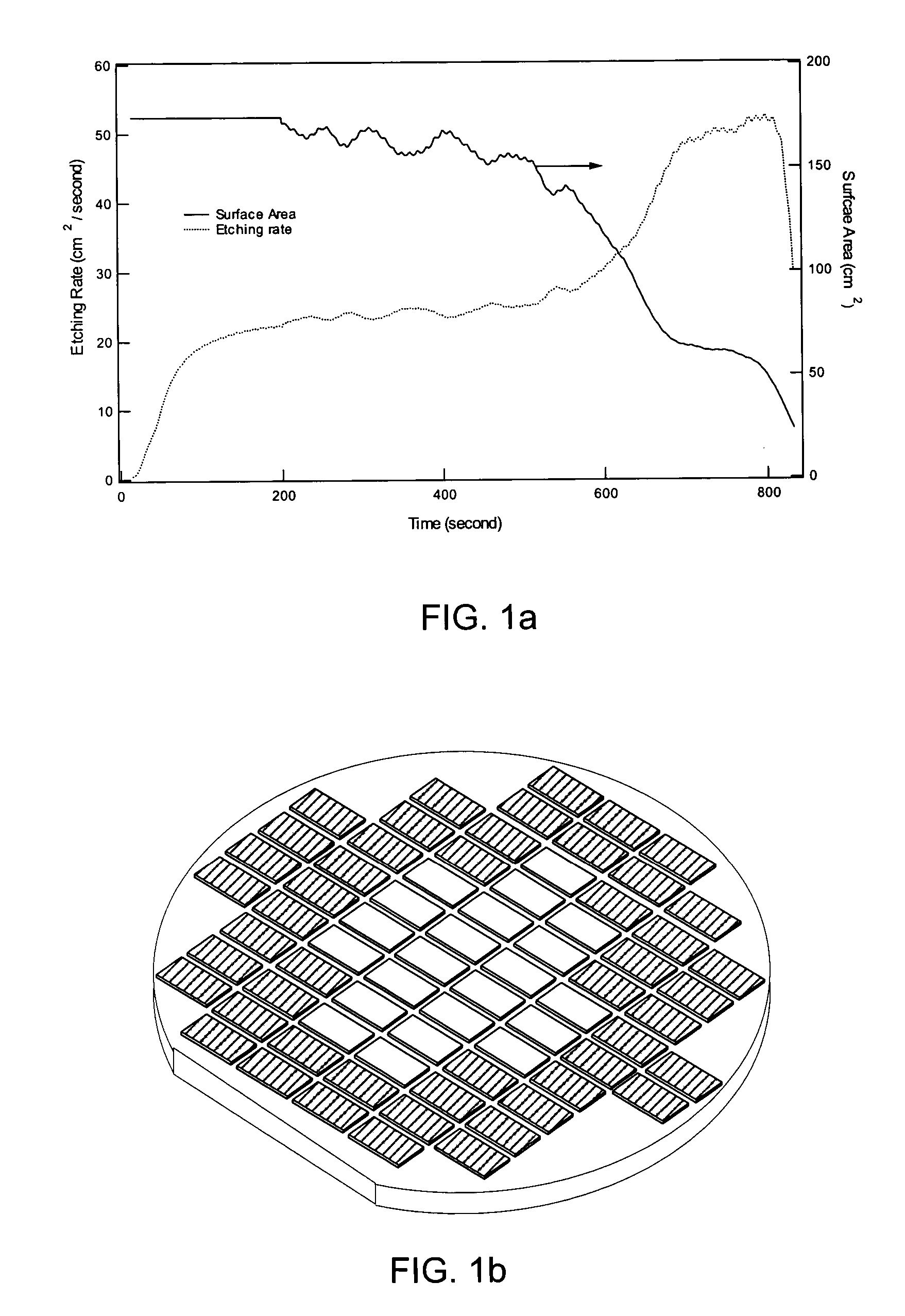
In addition to the disadvantages mentioned above, none of these etching processes addresses the issue of non-uniform etch due to the surface variation of the sacrificial material during etching processes.
Moreover, the microloading effect can result in etch rate variation within a single die.
Since the selectivity often depends upon the etching rate, unstable etching rate may result in etching non-uniformity to the microstructures.
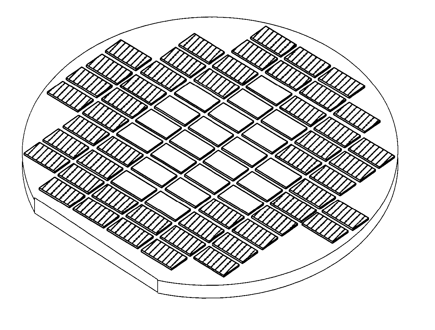
This etching rate difference may cause unexpected performance differences of the microstructures of the dies around the edge of the wafer and the microstructures of the dies close to the center of the wafer.

Method used


Image

  • Methods and apparatus of etch process control in fabrications of microstructures
  • Methods and apparatus of etch process control in fabrications of microstructures
  • Methods and apparatus of etch process control in fabrications of microstructures

Examples


Embodiment Construction

The present invention teaches a method for removing sacrificial materials in fabrications of microstructures using one or more selected spontaneous vapor phase etchants. During the etching process, the etching rate is controlled by feeding the etchant based on a detection of an amount of the etchant or an amount of etching product.

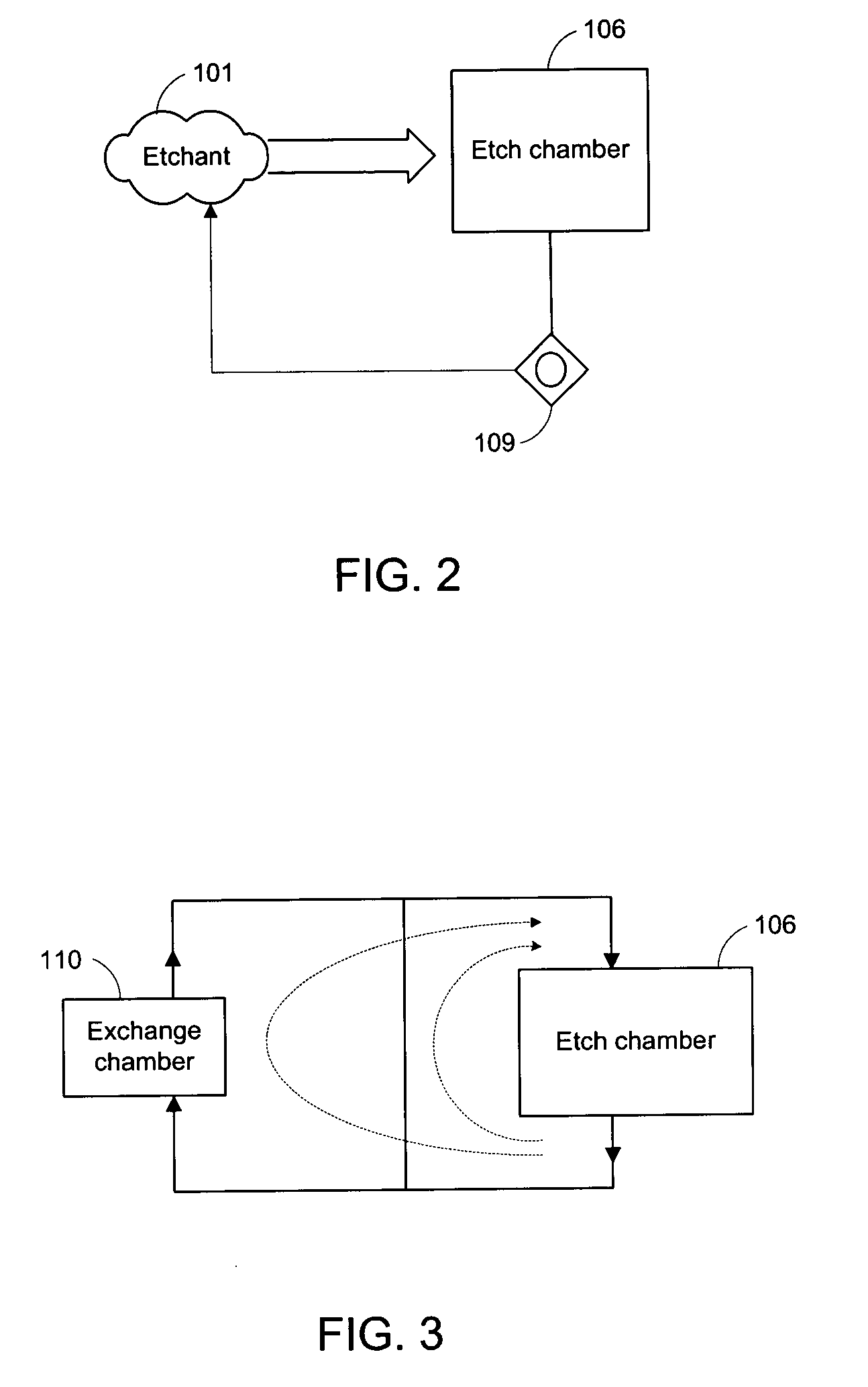
Referring to FIG. 2, etching chamber 106 and detector 109 are part of an etching system of the present invention. The detector is preferably connected downstream of the etch chamber and dynamically measures the concentration of a chemical species, such as the etchant or an etch product, flowing out of the etch chamber. The measured concentration is analyzed to obtain the etching process information, such as the etching rate (defined as the amount of the sacrificial material being removed per second) and / or etching product generation rate (defined as the amount of the etching product generated through the chemical reaction between the etchant and the sac...


PUM

PropertyMeasurementUnit
Fractionaaaaaaaaaa
Fractionaaaaaaaaaa
Partial pressureaaaaaaaaaa

Abstract

The present invention provides a method for removing sacrificial materials in fabrications of microstructures using a selected spontaneous vapor phase chemical etchants. During the etching process, an amount of the etchant is fed into an etch chamber for removing the sacrificial material. Additional amount of the etchant are fed into the etch chamber according to a detection of an amount or an amount of an etching product so as to maintaining a substantially constant etching rate of the sacrificial materials inside the etch chamber. Accordingly, an etching system is provided for removing the sacrificial materials based on the disclosed etching method.

Description

TECHNICAL FIELD OF THE INVENTION The present invention is related generally to the art of fabrications of microstructures which includes such devices as microelectromechanical systems, semiconductor devices, and, more particularly, to methods and apparatus of controlling etching processes in fabrications of the microstructures. BACKGROUND OF THE INVENTION Sacrificial layers of selected sacrificial materials are commonly used in fabrications of microstructures, such as microelectromechanical systems and semiconductor devices. One type of sacrificial material is amorphous silicon. Once the desired structures of the microstructure are formed, the sacrificial layers are removed by etching. The success of the etching process depends upon the selectivity of the etching process, wherein the selectivity is defined as a ratio of the amount of sacrificial material being removed to the amount of the structural material being removed. Performance, uniformity and yield can all be improved with...

Claims


Application Information

Patent Timeline
IPC IPC(8): B81C1/00C23F1/12H01LH01L21/00H01L21/302H01L21/311H01L21/3213H01L21/461
CPCB81C1/00531B81C2201/0109C23F1/12H01L21/67253H01L21/32135H01L21/67069H01L21/31116B81C2201/0138
Inventor SHI, HONGQINSCHAADT, GREGORY P.
Owner TEXAS INSTR INC
Learn More