
System and method for counting cars at night

Inactive Publication Date: 2005-03-17
HONEYWELL INT INC
View PDF6 Cites 27 Cited by
  • Summary
  • Abstract
  • Description
  • Claims
  • Application Information

AI Technical Summary

Benefits of technology

[0009] It is an object of this invention to provide a system and method that facilitates the identification of vehicles during periods of reduced visibility. It is a further object of this invention to provide such a system and method using conventional video cameras. It is a further object of this invention to facilitate the augmentation of existing video-based traffic monitoring systems to support day and night discrete vehicle identification and tracking.
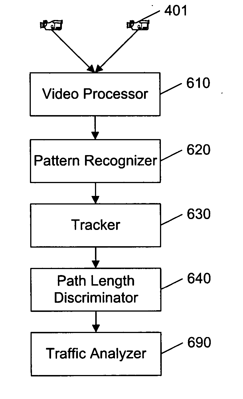
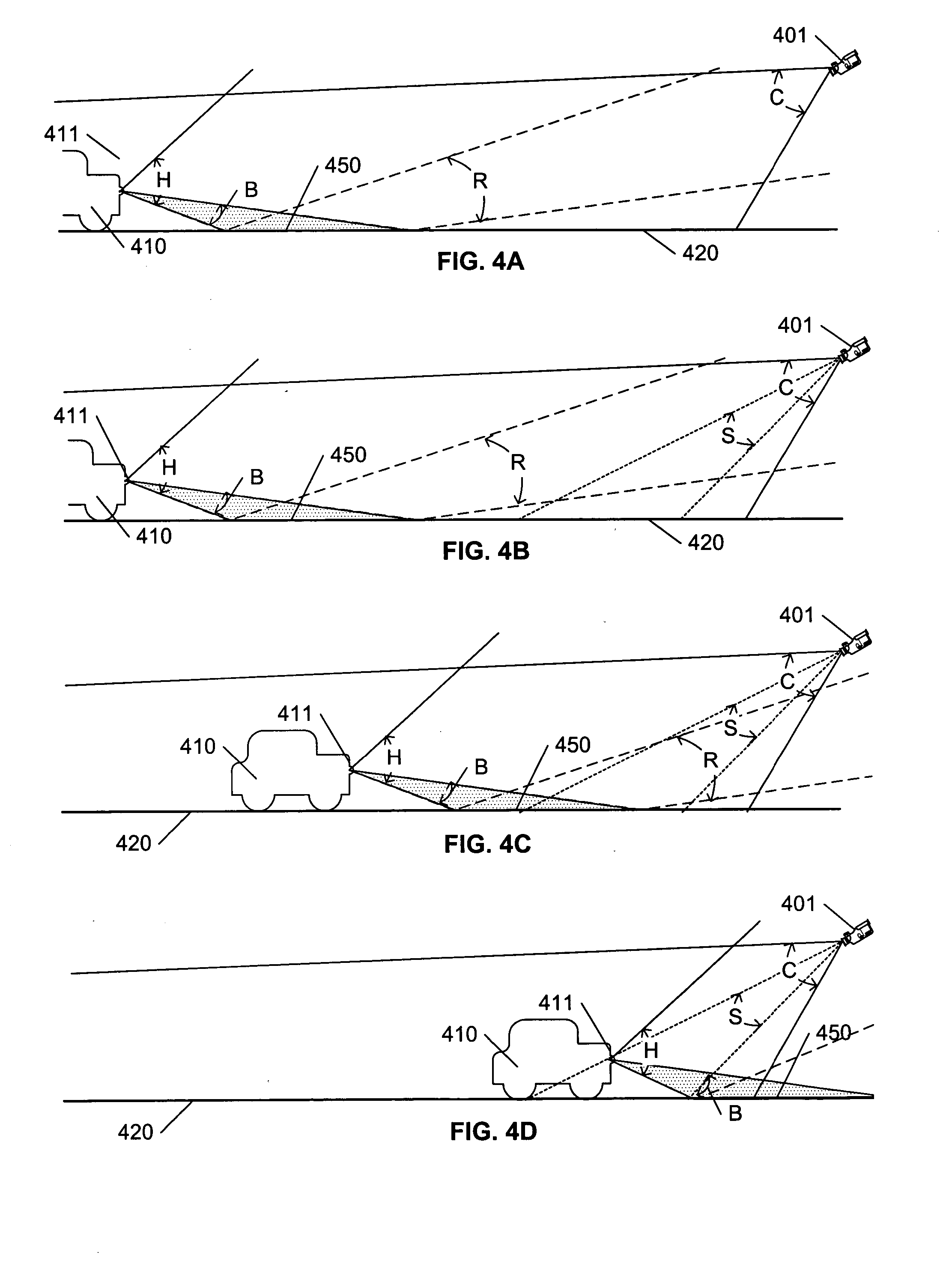
[0010] These objects, and others, are achieved by a vehicle identification system that distinguishes vehicles in reduced visibility conditions based on the characteristic tracks produced by vehicle headlights and their reflections. In a first aspect of this invention, vehicle headlights are distinguished from their reflections based on the length of the tracks produced by each. In a second aspect of this invention, recognition zones within a camera's field of view are identified that facilitate reliable recognition of headlight patterns. Recognizing that vehicle headlights exhibit a characteristic projection pattern, and that the appearance of reflections of headlight beams in a camera image is highly dependent upon the angle of incidence / reflection relative to the camera, whereas the appearance of the headlights in the image is relatively consistent, the recognition zones are selected as regions in the camera image that are not likely to provide reflections from normally aligned headlight beams. Pattern-matching and motion-correlation techniques are also used to identify the track of each vehicle in prior and subsequent image frames.

Problems solved by technology

Identifying vehicles in reduced visibility situations, particularly after dark, is particularly problematic.
If the monitored segment of roadway is brightly lit, the conventional image recognition algorithms generally operate effectively, but if the segment is not brightly lit, the conventional image recognition algorithms are unable to accurately distinguish vehicles.
In a dark environment, colors and / or luminance differences are not distinguishable, and the conventional edge-detection algorithms fail to accurately distinguish shapes that correspond to the shape of the moving vehicles.
The conventional motion-detection algorithm will also exhibit anomalous behavior, as items will appear and disappear in sequential images, depending upon their illumination by passing vehicles' headlights.
Although pattern-recognition techniques may be employed to distinguish vehicles by distinguishing pairs of uniformly moving headlights, such techniques are susceptible to misidentifications caused by reflections, such as the reflection of headlights on a wet roadway at night.
Such a deployment of infrared or night-vision cameras increase the cost of such vehicle monitoring systems.
If a video system is already deployed, the cost of adding infrared or night-vision devices includes the cost of the additional cameras and their installation, as well as the cost to access and modify the existing installation to facilitate the installation.

Method used


Image

  • System and method for counting cars at night
  • System and method for counting cars at night
  • System and method for counting cars at night

Examples


Embodiment Construction

[0022] The invention is presented herein using the paradigm of a traffic analysis system that is configured to count vehicles on a roadway at night. One of ordinary skill in the art will recognize that the examples presented herein are intended for ease of presentation and understanding, and that the principles presented herein are not limited to this example application.

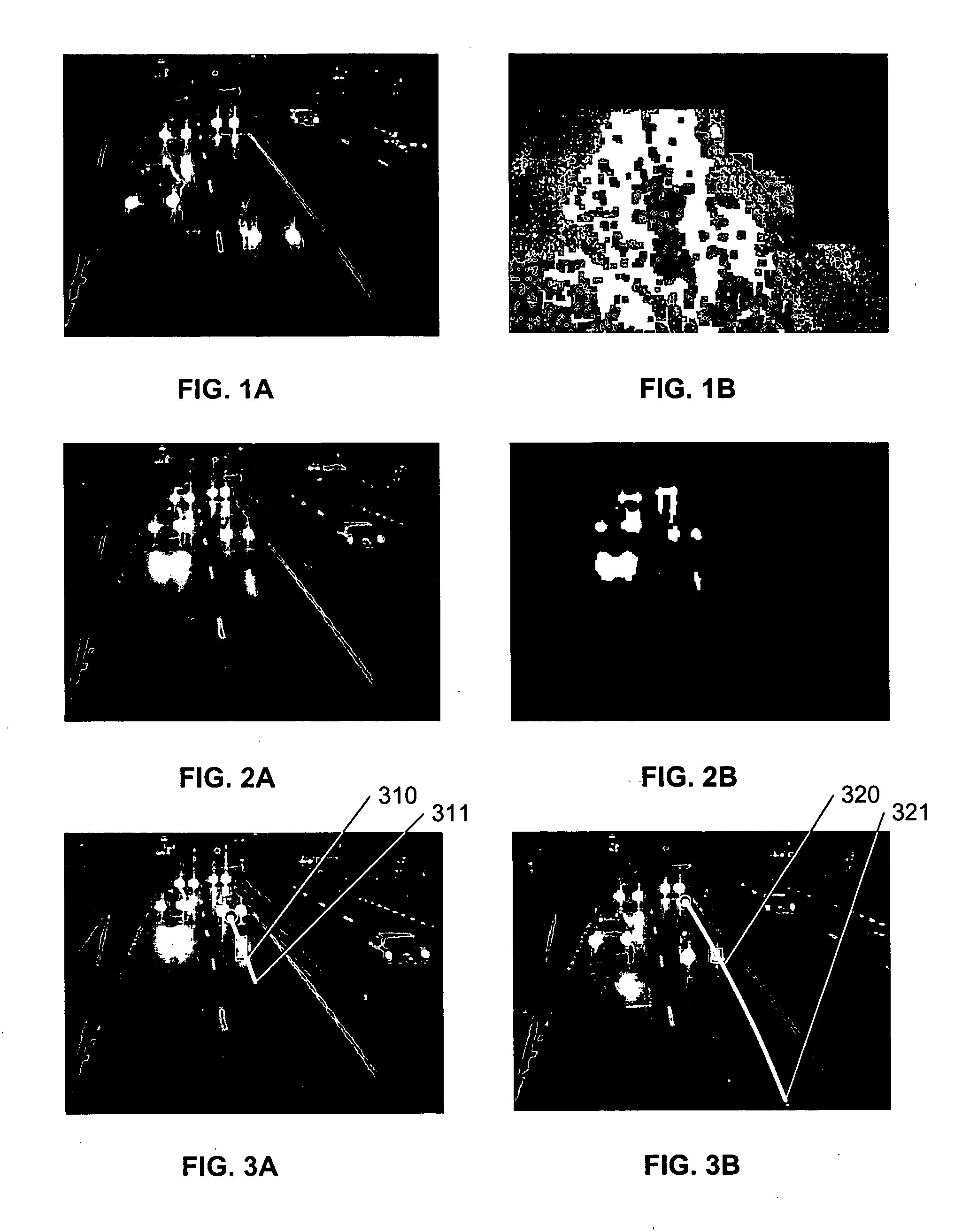
[0023]FIGS. 1A and 1B illustrate the difficulties associated with attempting to recognize shapes in a typical image of a roadway at night. Because of the reduced overall lighting level, and the contrast provided by vehicle headlights, it is difficult to clearly determine the shape of each vehicle in FIG. 1A.

[0024]FIG. 1B illustrates the results of a conventional background-subtraction processing of the image of FIG. 1A. In this example, FIG. 1B is created by detecting differences between the image of FIG. 1A and a reference model of the scene without vehicles. A shadow detection process is also typically employed,...


PUM


Abstract

A vehicle identification system distinguishes vehicles in reduced visibility conditions based on the characteristic projection patterns associated with vehicle headlights and their reflections. Recognizing that the appearance of reflections of headlight beams in a camera image is highly dependent upon the angle of incidence / reflection relative to the camera, whereas the appearance of the headlights in the camera image is relatively consistent, the vehicle identification system distinguishes vehicles from their reflections based on the tracks of the illumination patterns in a series of images. In a first embodiment, headlights are distinguished from reflections based on a length of the tracks. In a second embodiment, recognition zones are selected as regions in the camera image that are not likely to provide reflections from normally aligned headlight beams. Pattern-matching and motion-correlation techniques are also used to identify the track of each vehicle in prior and subsequent image frames.

Description

[0001] This application claims the benefit of U.S. Provisional Application 60 / 502,823, filed 12 Sep. 2003.BACKGROUND OF THE INVENTION [0002] 1. Field of the Invention [0003] This invention relates to the field of computer vision, and in particular to a system and method for counting vehicles on roadways during periods of reduced visibility. [0004] 2. Description of Related Art [0005] Cameras are conventionally used to monitor traffic flow. Coupling a video processing system to cameras that monitor traffic flow can facilitate traffic flow analysis and other traffic related studies. Such analyses and studies typically require a determination of the number of vehicles traveling on a particular stretch of road, the number of vehicles entering or exiting a road at a particular intersection, the number of vehicles exhibiting a particular driving pattern, and so on. In order to provide an accurate count of vehicles, each vehicle must be distinguished from each other vehicle, and often the ...

Claims


Application Information

Patent Timeline
IPC IPC(8): G06K9/00G06K9/32
CPCG06K9/3241G06V10/255
Inventor BRODSKY, TOMAS
Owner HONEYWELL INT INC
Learn More