
Data storage system with a removable backplane having a array of disk drives

Active Publication Date: 2005-03-17
NETWORK APPLIANCE INC
View PDF6 Cites 54 Cited by
  • Summary
  • Abstract
  • Description
  • Claims
  • Application Information

AI Technical Summary

Benefits of technology

[0011] The present invention overcomes the disadvantages and limitations of previous solutions by providing a system and method for mounting an array of disk drives in a vertical manner on a backplane in an elongated rectangular prismatic enclosure that provides access through one of the smaller faces of the enclosure. The backplane may be oriented parallel to the direction of access and so as to not impede the flow of air through the enclosure. The backplane and the disk drives may be removable as a unit from the enclosure.
[0014] The advantages of the present invention are that many more disk drives may be populated in the same volume of a rack mounted enclosure, thereby providing a much higher storage capacity than other solutions. Further, the removable backplane and disk array may be a sealed replaceable unit that is removable as a single unit.

Problems solved by technology

The midplane board poses several problems for a designer.
First, the board can be a single point of failure for the entire rack mounted unit.
Second the midplane board often poses substantial restrictions on airflow, since the midplane board is generally oriented perpendicular to the conventional airflow through a rack mounted box.
The depth of a rack mounted case may be 18 or more inches deep, yet a removable disk drive mounted on a carrier may be 6 inches deep, leaving a significant amount of room that cannot be used for removable disk drives.

Method used


Image

  • Data storage system with a removable backplane having a array of disk drives
  • Data storage system with a removable backplane having a array of disk drives
  • Data storage system with a removable backplane having a array of disk drives

Examples


embodiment 100

[0019]FIG. 1 illustrates an embodiment 100 of the present invention showing a disk array. An enclosure 102 has a removable backplane 104 that contains an array of disk drives 106.

[0020] The embodiment 100 provides a mechanical packaging solution for a multiple disk drive storage device that allows many disk drives to be accessed through one of the smaller sides of the enclosure. Further, the embodiment 100 allows for multiple rows and columns of disk drives to fill an enclosure, which provides a much higher number of disk drives than other solutions where each disk drive must be individually accessible from the access side 108 of the enclosure.

[0021] The backplane 104 may be constructed or mounted in a way so that it may be removed through the access side 108 of the enclosure. Various sliding rails, guides, carriers, bearings, or other mechanical device may be used by those skilled in the arts to effect the general sliding motion of the backplane 104 into and out from the enclosure...

embodiment 200

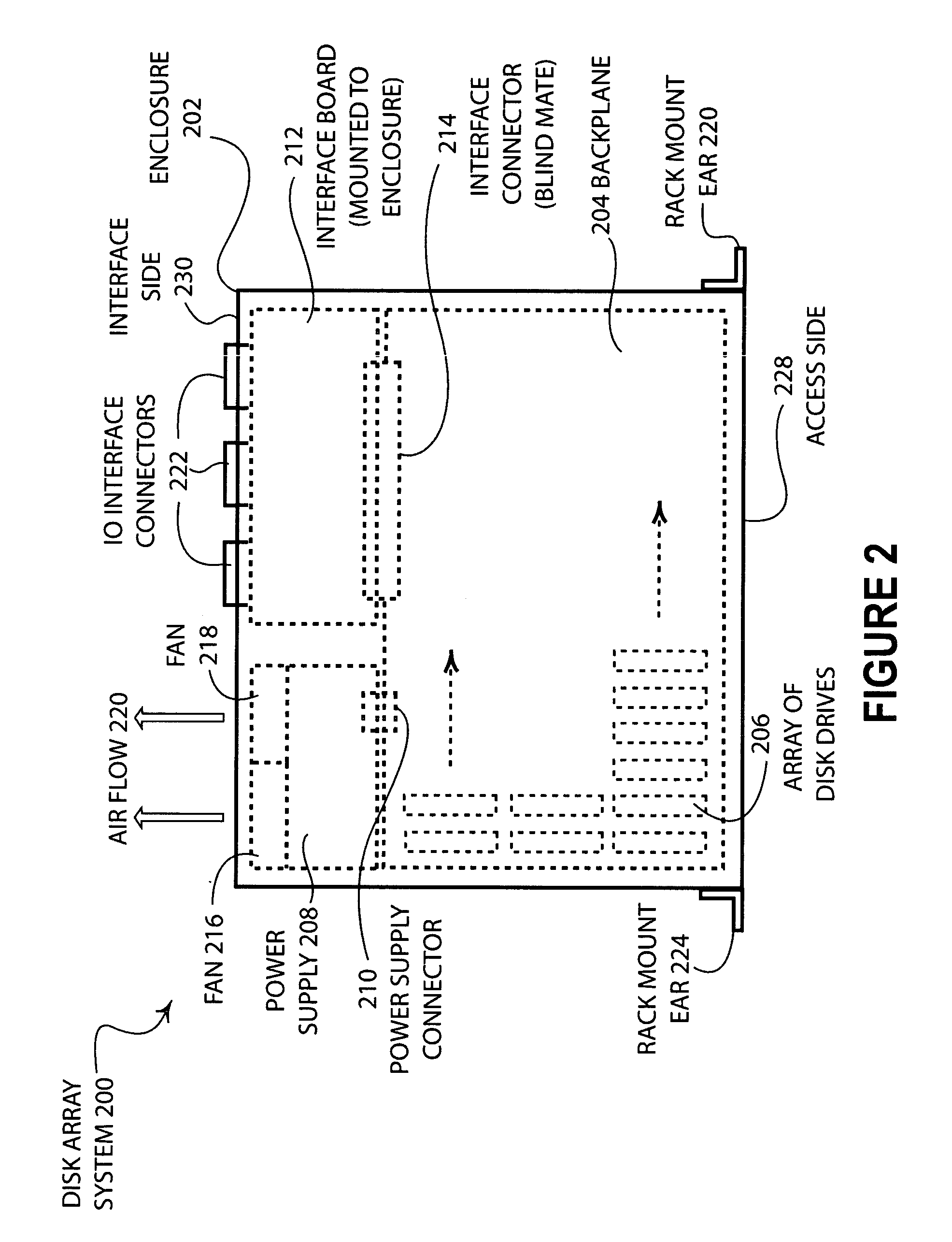
[0030]FIG. 2 illustrates an embodiment 200 of the present invention showing a top view of a rack mounted disk array. An enclosure 202 has a backplane 204 with a disk drive array 206 mounted thereon. The backplane 204 interfaces to the power supply 208 through a power supply connector 210 and the interface board 212 through the interface connector 214. The enclosure 202 has rack mount ears 224 and 226 that enable simple mounting of the enclosure 202 to a standard sized equipment rack.

[0031] The power supply 208 may have fans 216 and 218 that produce airflow 220 through the enclosure 202. The disk drives 206 may be arranged as illustrated so as not to impede the airflow 220 through the enclosure. In such an embodiment, the access side 228 of the enclosure 202 may be perforated or otherwise facilitate airflow through the enclosure. In some embodiments, those skilled in the art will recognize that it may be advantageous to provide airflow in the opposite direction from the airflow 220. ...

embodiment 300

[0038]FIG. 3 illustrates an embodiment 300 of the present invention showing a disk array with a removable unit. The enclosure 302 has an access side 303 into which a frame 304 may be inserted. The frame 304 may contain a backplane 306 and an array of disk drives 308. The frame 304 may have a cover 310.

[0039] The frame 304 may be inserted into the enclosure 302 in order to electrically engage the backplane 306 into an interface board (not shown) located inside the enclosure 302. The frame 304 may allow the backplane 306 and the disk drives 308 to be handled and transported outside of the enclosure 302 without risk of damage.

[0040] The frame 304 may be adapted with guides, slides, or other mechanisms to guide the frame 304 into the enclosure. In some embodiments, the frame 304 may be mounted on slides or other devices so that the frame 304 remains connected to the enclosure 302 even when the frame 304 is drawn out of the enclosure 302. In other embodiments, the frame 304 may be a rem...


PUM


Abstract

An array of disk drives may be mounted onto a backplane that may slide as a single unit into an enclosure, such as a rack mounted enclosure. The backplane may allow the disk drives to be arranged in multiple columns and rows such that the disk drives are generally parallel to each other. Such an arrangement affords excellent airflow around the disk drives and greatly simplifies servicing of the disk array.

Description

CROSS REFERENCE TO RELATED APPLICATIONS [0001] This application is simultaneously filed with U.S. patent application Ser. No. ______ entitled “Storage Recovery Using a Delta Log”, attorney docket number LSI.81US01 (03-1078), by Mohamad El-Batal, et al and U.S. patent application Ser. No. ______ entitled “Disk Storage System with Removable Arrays of Disk Drives”, attorney docket number LSI.78US01 (03-1076), by Mohamad El-Batal, et al, the entire contents of which are hereby specifically incorporated by reference for all they disclose and teach.BACKGROUND OF THE INVENTION [0002] a. Field of the Invention [0003] The present invention pertains to data storage systems and specifically to data storage systems having multiple disk drives operable in a single device. [0004] b. Description of the Background [0005] Multiple disk drives are an essential component in today's large data storage systems. Often, multiple individual disk drives may be configured in many different storage systems in...

Claims


Application Information

Patent Timeline
IPC IPC(8): G11B33/02G11B33/12
CPCG11B33/022G11B33/128G11B33/126
Inventor EL-BATAL, MOHAMADWEBER, BRETNOSSOKOFF, MARK
Owner NETWORK APPLIANCE INC
Learn More