
System and method for locating and determining discontinuities and estimating loop loss in a communications medium using frequency domain

a communication medium and frequency domain technology, applied in the field of information communication system testing, can solve problems such as non-uniformities in telecommunications mediums, tdr implementation of twisted pair and similar dispersive channels, and progressively lost probe signal energy, so as to mitigate baseline effects of response signals and mitigate dispersion effects

Inactive Publication Date: 2005-03-17
SPIRENT COMM
View PDF31 Cites 35 Cited by
  • Summary
  • Abstract
  • Description
  • Claims
  • Application Information

AI Technical Summary

Benefits of technology

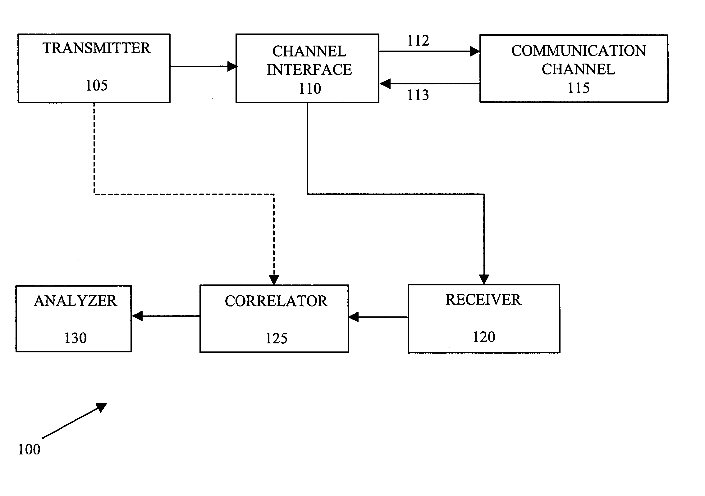
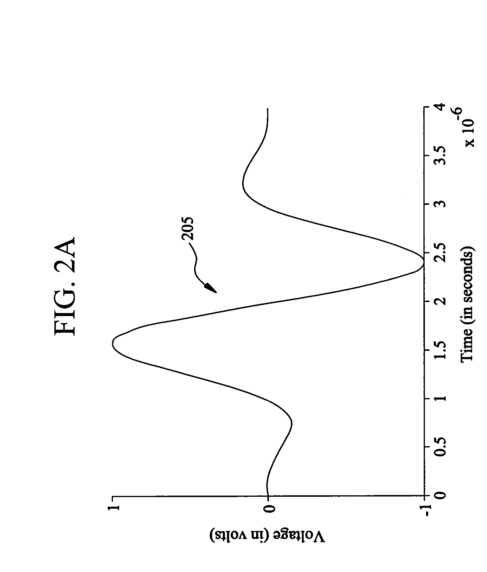
According to the first aspect, the analyzer can identify correlation peaks by determining where magnitudes of the frequency domain correlation information exceed at least one predetermined threshold function. The analyzer can determine a type of a located discontinuity from among a plurality of types of discontinuities by comparing an amplitude of the identified correlation peak with each of a plurality of predetermined threshold functions. Each type of discontinuity can be associated with one of the plurality of predetermined threshold functions. According to the first aspect, the first signal can comprise a stimulus signal. The transmitter can comprise a stimulus generator for generating the stimulus signal. The second signal can comprise at least one reflection of the stimulus signal from at least one discontinuity of the communication channel. The stimulus signal can comprise a narrowband stimulus signal. The narrowband stimulus signal can mitigate effects of dispersion associated with the communication channel. The stimulus generator can adaptively determine a packet length of the narrowband stimulus signal based on attenuation associated with the communication channel. The narrowband stimulus signal can comprise sine packets windowed by, for example, a Blackman-Harris function.
According to a tenth aspect of the present invention, a stimulus-response method for determining characteristics associated with a communication channel comprises the steps of: i.) generating a stimulus signal, wherein the stimulus signal comprises a narrowband stimulus signal, and wherein the narrowband stimulus signal mitigates effects of dispersion associated with the communication channel; and ii.) receiving a response signal via the communication channel in response to the narrowband stimulus signal, wherein the response signal comprises at least one reflection of the narrowband stimulus signal from at least one discontinuity of the communication channel.

Problems solved by technology

Non-uniformities in the telecommunications medium exist, and probe signal energy is lost progressively as a function of distance traveled in the medium, due to the unavoidable dissipative characteristics of the medium material.
This can pose a problem for the TDR implementation for twisted-pair and similar dispersive channels.
Since a large number of frequency components exist, the overall effect is that the reflected signal becomes smeared out, making it difficult to determine the starting time of the reflection and, hence, the location of the discontinuity.
Similarly, since the attenuation of the received signal is comprised of compound effects from components from a large frequency range, especially the low frequency range, it becomes difficult to determine the round-trip loss of the communication channel.
The different phase velocities at different frequencies lead to dispersion of signal energy and to inter-symbol interference.
Since the stimulus is a broadband signal, it is extremely difficult to find a phase velocity that is suitable for all different lengths and structures of transmission lines.
The reason for the difficulty is that the extremely high attenuation of the high frequency components for the long line leads to components at lower frequency band dominating the reflected signal.
Use of the high-pass filter can result in the attenuation of frequency components up to a certain frequency (depending on the high-pass filter used).
However, generally large amounts of low-pass frequency components will still exist.
The dispersion in the twisted-pair channel can then still make localization of a discontinuity difficult.
Thus, the attenuation distortion and dispersion can adversely affect the accuracy of traditional TDR measurements.

Method used


Image

  • System and method for locating and determining discontinuities and estimating loop loss in a communications medium using frequency domain
  • System and method for locating and determining discontinuities and estimating loop loss in a communications medium using frequency domain
  • System and method for locating and determining discontinuities and estimating loop loss in a communications medium using frequency domain

Examples


Embodiment Construction

A system and method are disclosed for determining characteristics associated with a communication channel. In accordance with an exemplary embodiment of the present invention, Blackman-Harris windowed sine packets or other narrowband signals can be used as the stimulus for a time domain reflectometer (TDR) to address the dispersion of the communication channel. The stimulus is reflected back when it encounters discontinuities, such as an open, short, bridge tap or other discontinuities, in the communication channel. A frequency domain correlation routine can be applied to detect the location of these discontinuities. The frequency domain correlation routine can correlate Fourier transforms of the reflected signals with Fourier transforms of a series of time-delayed versions of the stimulus in the frequency domain, and then determine the location of the discontinuities by searching for the peaks of the magnitude of the frequency domain correlation results. The nature of the discontin...


PUM


Abstract

A system for determining characteristics associated with a communication channel includes a transmitter for transmitting a first signal via the communication channel. The system includes a receiver for receiving a second signal via the communication channel in response to the first signal. The second signal is associated with the first signal. The system includes a correlator for performing frequency domain correlation between a frequency domain representation of the second signal and frequency domain representations of a plurality of time-delayed versions of the first signal to generate frequency domain correlation information. The system includes an analyzer for identifying correlation peaks in a magnitude of the frequency domain correlation information to determine locations of discontinuities of the communication channel. The identified correlation peaks are associated with the locations of the discontinuities of the communication channel.

Description

BACKGROUND 1. Field of the Invention The present invention relates to testing of information communication systems. More particularly, the present invention relates to a system and method for locating and determining discontinuities and estimating loop loss in a communications medium using frequency domain correlation. 2. Background Information A time domain reflectometer (TDR) operates by abruptly stimulating an object under test, and subsequently, over time, recording the elicited responses. Typically, the subject object is a medium designed for the propagation of energy from point to point in some form, such as, for example, sound, light or electricity. One type of TDR can analyze the electrical propagation characteristics of extended lengths of twisted pairs of wires, as are commonly used to transport telecommunications signals. Such a TDR is designed to interface with twisted pair wire lines that are deployed as a subscriber loop plant (the pair of leads over which each sub...

Claims


Application Information

Patent Timeline
Patent Type & Authority Applications(United States)
IPC IPC(8): G01R31/11H04B17/00H04L25/02
CPCG01R31/11H04B17/309H04L25/0202
Inventor BAILEY, GEORGE R.ZHOU, TERRY
Owner SPIRENT COMM
Learn More