
Continuously threaded hold-down system

a technology of hold-down system and threaded thread, which is applied in the direction of fastening means, mechanical equipment, washing machines, etc., can solve the problems of isolating each individual level of the building, and the hold-down system may not be continuously threaded, so as to achieve convenient and quick installation

Active Publication Date: 2005-03-17
COMMINS ALFRED D
View PDF21 Cites 51 Cited by
  • Summary
  • Abstract
  • Description
  • Claims
  • Application Information

AI Technical Summary

Benefits of technology

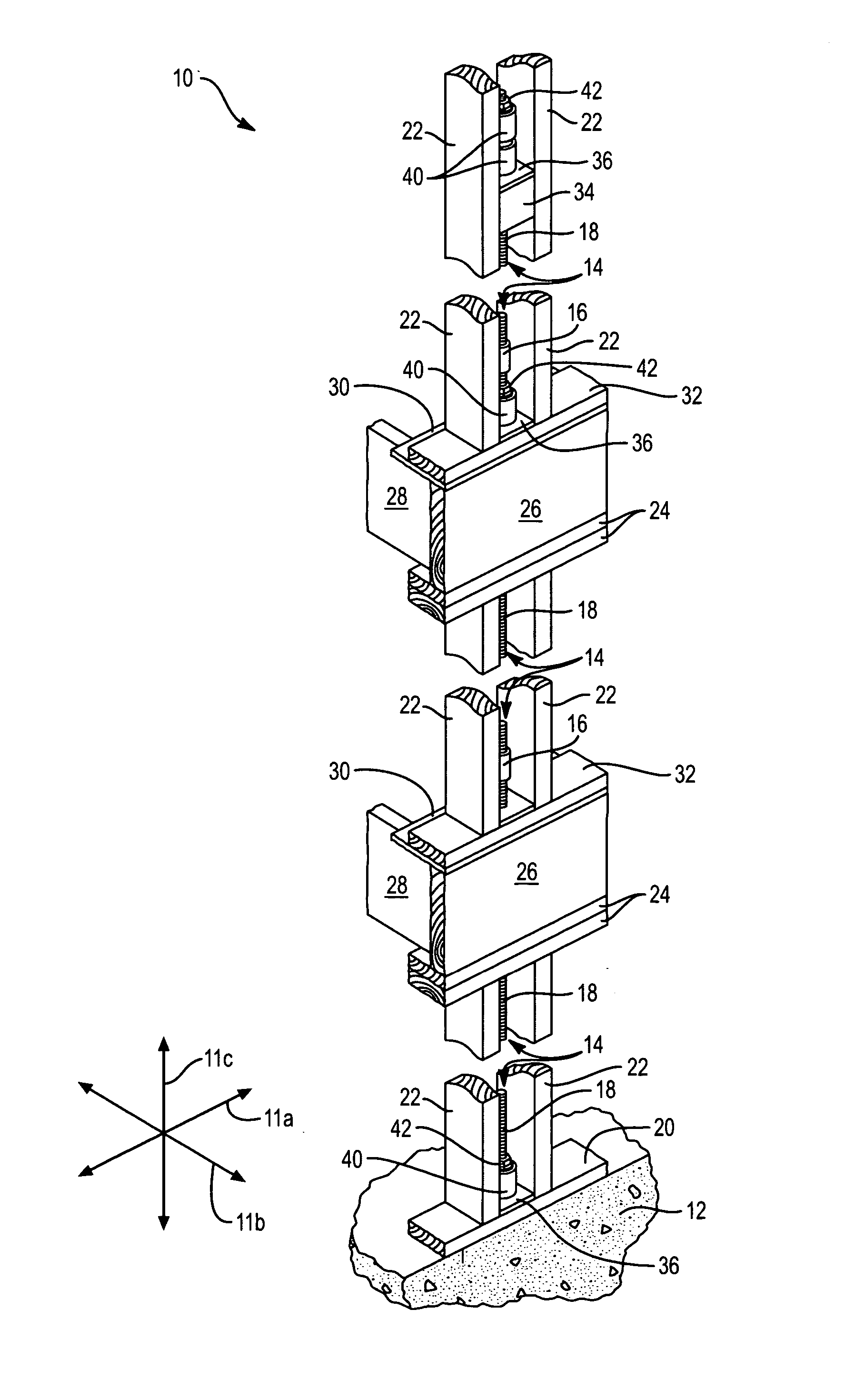
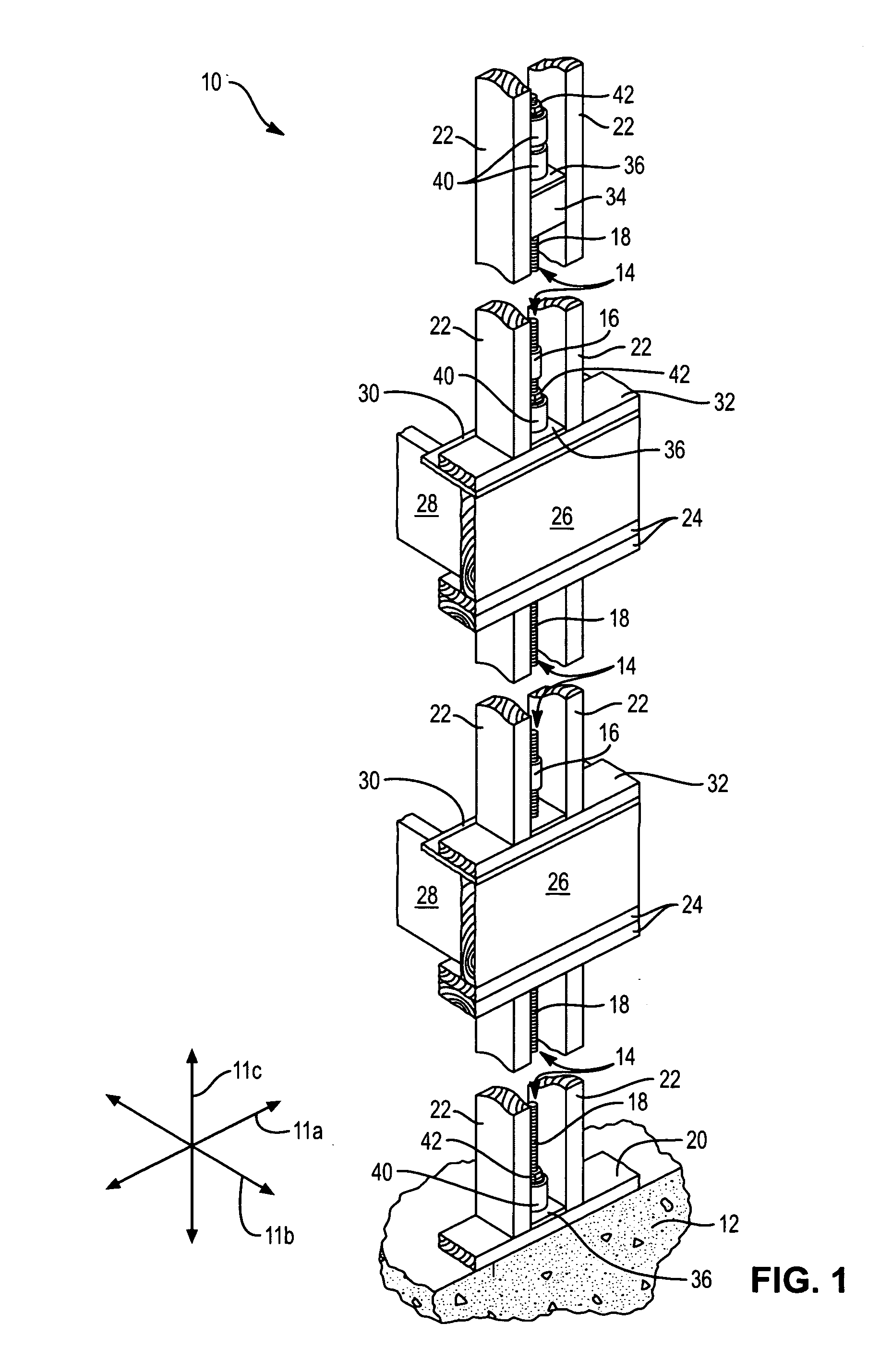
[0011] It is an object of the present invention to provide a continuously threaded hold-down system that may be easily and quickly installed.
[0012] It is a further object of the present invention to provide a hold-down system that may be mass produced inexpensively.
[0013] In certain embodiments, the apparatus and method in accordance with the present invention may include a foundation with an anchor, which anchor is composed of threaded rods coupled together and extending through one or more levels of a building or structure. The anchor provides a basis for the individual components of the continuously threaded hold-down system. The take-up units used in the system help maintain tension throughout the system, essentially securing the entire structure to the foundation. Securing the structure to the foundation enables the structure to better withstand various forces acting on the structure. These forces are transferred to the foundation where they can be dissipated more efficiently.
[0014] While previous hold-down systems may be considered useful for similar purposes, the continuously threaded hold-down system described herein is a more effective and efficient system. Previous hold-down systems may not be continuously threaded, thereby isolating each individual level of the building. The continuously threaded nature of the current invention allows the system to compensate for shrinkage or crushing which may occur on any level of the building. Thus, if shrinkage or crushing on one level exceeds the capacity of the system on that level, the system on other levels can compensate for the excess.
[0015] Another feature of this particular continuously threaded hold-down system is that the individual take-up units used in the system are stackable, more than one take-up unit may be stacked providing greater ability to compensate for shrinkage and crushing. This is especially helpful in the continuously threaded system because the system is capable of compensating for shrinkage and crushing which may occur on any level of the building. Therefore, if the top level of the building has a couple of take-up units stacked on top of each other, those units can compensate for any excess shrinkage or crushing throughout the building. This can also be especially helpful on upper levels of a building because shrinkage and crushing that may occur on lower levels tend to be accentuated on upper levels.

Problems solved by technology

Previous hold-down systems may not be continuously threaded, thereby isolating each individual level of the building.

Method used


Image

  • Continuously threaded hold-down system
  • Continuously threaded hold-down system
  • Continuously threaded hold-down system

Examples


Embodiment Construction

[0031] It will be readily understood that the components of the present invention, as generally described and illustrated in the Figures herein, may be arranged and designed in a wide variety of different configurations. Thus, the following more detailed description of the embodiments of the system and method of the present invention, as represented in FIGS. 1 through 11, is not intended to limit the scope of the invention. The scope of the invention is as broad as claimed herein. The illustrations are merely representative of certain, illustrative embodiments of the invention. Those embodiments of the invention will be best understood by reference to the drawings, wherein like parts are designated by like numerals throughout.

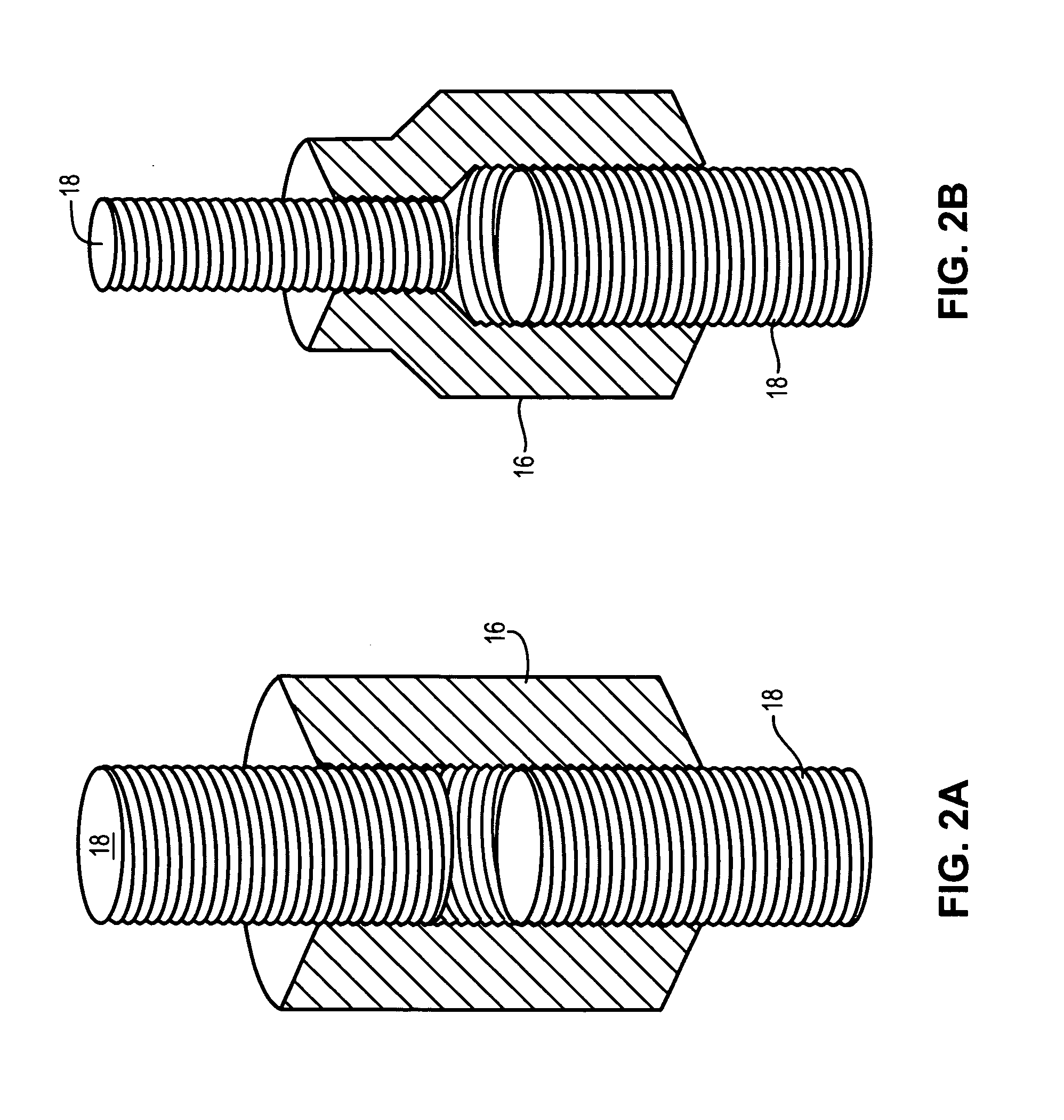
[0032] Several Figures display an automatic take-up unit. This device is described fully in U.S. Pat. No. 6,390,747 issued May 21, 2002, to this inventor, and incorporated herein by reference.

[0033] Those of ordinary skill in the art will, of course, apprecia...


PUM


Abstract

A hold-down system used to secure a building structure to the foundation, thereby enabling the building to better withstand forces like high winds and earthquakes because these forces may then be distributed to the foundation. The hold-down system is characterized as being continuously threaded and having stackable, individual take-up units. A continuously threaded hold-down system allows the system to compensate for shrinkage or crushing of the building's frame throughout each level of the building because the anchor of the system is always in communication with the foundation of the building. The individual take-up units are stackable allowing each level of the system to compensate for shrinkage or crushing on that level as well as adjacent levels.

Description

BACKGROUND [0001] 1. Field of the Invention [0002] The present invention relates to building construction, and more specifically, to apparatus for anchoring shear walls to foundations and lower floors. [0003] 2. Background [0004] Strong winds and earthquakes subject walls and others elements of a building to tremendous forces. If these forces are not distributed to the proper elements or structures capable of withstanding such force, the building may be torn apart. Foundations are often the strongest element of a building. Securely tying the walls of a building to the foundation greatly improves structural performance during periods of strong wind or earthquake. Securement promotes single body motion and limits whiplash amplification that often results in structural failure. [0005] Under extreme conditions, a building may be violently loaded or shaken back and forth in a lateral (side to side) direction. If a shear wall is tightly restrained at its base, loads may be smoothly transf...

Claims


Application Information

Patent Timeline
IPC IPC(8): E02D27/00E02D27/32E02D27/42E04B1/00E04B1/26E04B1/35E04H9/14
CPCE04B1/26E04B1/2604E04B2001/268E04H9/14E04B2001/2688E04B2001/2696E04B2001/3583E04B2001/2684
Inventor COMMINS, ALFRED D.
Owner COMMINS ALFRED D
Learn More