
Method and apparatus for intrachamber resynchronization

Inactive Publication Date: 2005-03-10
MIROWSKI FAMILY VENTURES LLC
View PDF95 Cites 23 Cited by
  • Summary
  • Abstract
  • Description
  • Claims
  • Application Information

AI Technical Summary

Benefits of technology

[0014] In another embodiment, a plurality of electrodes are implanted in the left ventricle to stimulate at multiple locations in the left ventricle for the purpose of improving hemodynamic performance and increasing cardiac output in a patient who is suffering from congestive heart failure. Electrodes may be implanted in the interventricular septum, in the coronary sinus, in a coronary vein in the left ventricle, in the epicardial wall of the left ventricle, or in any location suitable for stimulating the left ventricle without causing harm to the patient.
[0015] Two other techniques for improving cardiac output may also be used with the system and method of the present invention. First, an anodal or cathodal pre-excitation voltage may be applied to pre-condition a portion of the heart. Second, a field stimulation pulse of increased current (on the order of approximately 10 milliamps) may also be applied to improve cardiac output.

Problems solved by technology

A heart may suffer from one or more cardiac defects that interfere with the rhythmic cycle or conduction of electrical impulses.
Other conditions, such as myocardial scarring and bundle branch block, may slow conduction of impulses, and thus, cause the heart to beat in an uncoordinated fashion.
However, there are cardiac deficiencies that may interfere with the proper contraction within a particular chamber.
For example, a chamber may suffer from a defect or injury that blocks the propagation of electrical impulses within the chamber or prevents a portion of the chamber from contracting in a coordinated fashion with other chambers of the heart.
As another example, patients with congestive heart failure (CHF) may experience sufficient asynchrony within a single chamber of the heart that the chamber is unable to properly pump blood within a normal rhythmic cyle.
Unfortunately, known artificial pacemakers cannot completely compensate for asynchrony within a single chamber.

Method used


Image

  • Method and apparatus for intrachamber resynchronization
  • Method and apparatus for intrachamber resynchronization
  • Method and apparatus for intrachamber resynchronization

Examples


Embodiment Construction

[0001] 1. Field of the Invention

[0002] The present invention relates to medical devices, and in particular, to methods and apparatus for controlling contraction of a heart.

[0003] 2. Background

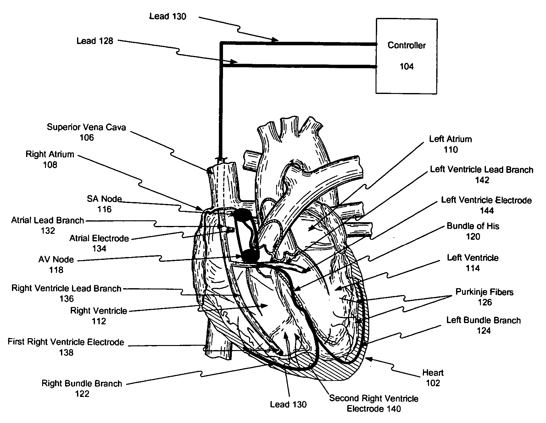
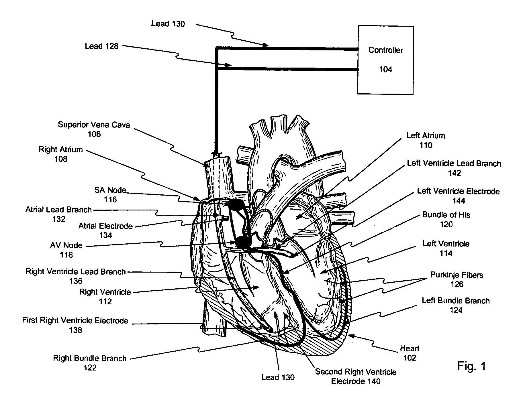
[0004] During a normal heartbeat, the heart contracts in a coordinated fashion to pump blood. In particular, the heart contracts based on rhythmic electrical impulses, which are spread over the heart using specialized fibers. These rhythmic electrical pulses are initiated by the heart's natural pacemaker called the sino-atrial node (“SA node”). The SA node initiates electrical impulses to cause the right and left atria to contract. As the atria contract, the electrical impulses from the SA node propagate to the atrial-ventricular node (“AV node”). The time these impulses take to propagate from the SA node through the AV node is known as the A-V delay. The A-V delay allows the atria to fully contract and fill the ventricles with blood.

[0005] The AV node then transmits the impulse, which caus...


PUM


Abstract

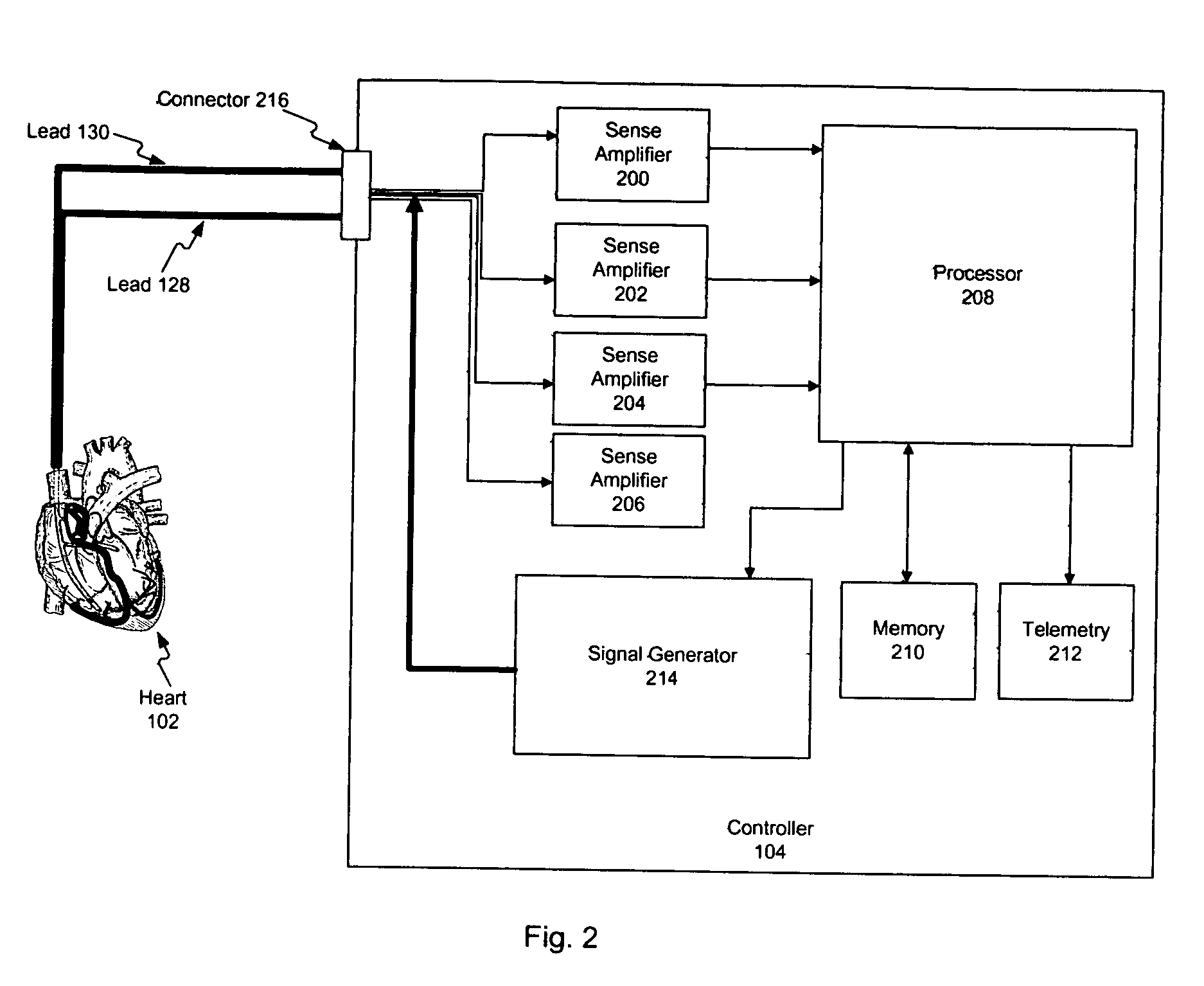
Methods, apparatus, and systems are provided to control contraction of the heart. At least one sensing element receives signals indicating electrical activity of sinus rhythm of the heart. Based on the received signals, the progress of contraction of the heart is determined. Based on the progress of contraction, the chamber of the heart may then be stimulated at a plurality of locations. In another embodiment, a plurality of electrodes are implanted in the left ventricle to stimulate at multiple locations in the left ventricle for the purpose of improving hemodynamic performance and increasing cardiac output in a patient who is suffering from congestive heart failure. A pre-excitation voltage may be applied to pre-condition a portion of the heart. A stimulation pulse of increased current may also be applied to improve cardiac output.

Description

DESCRIPTION OF THE INVENTION [0001] 1. Field of the Invention [0002] The present invention relates to medical devices, and in particular, to methods and apparatus for controlling contraction of a heart. [0003] 2. Background [0004] During a normal heartbeat, the heart contracts in a coordinated fashion to pump blood. In particular, the heart contracts based on rhythmic electrical impulses, which are spread over the heart using specialized fibers. These rhythmic electrical pulses are initiated by the heart's natural pacemaker called the sino-atrial node (“SA node”). The SA node initiates electrical impulses to cause the right and left atria to contract. As the atria contract, the electrical impulses from the SA node propagate to the atrial-ventricular node (“AV node”). The time these impulses take to propagate from the SA node through the AV node is known as the A-V delay. The A-V delay allows the atria to fully contract and fill the ventricles with blood. [0005] The AV node then tran...

Claims


Application Information

Patent Timeline
IPC IPC(8): A61N1/362A61N1/368
CPCA61N1/3627A61N1/36592A61N1/3684A61N1/36842A61N1/36843
Inventor MOWER, MORTON M.
Owner MIROWSKI FAMILY VENTURES LLC
Learn More