Radio receiver, radio transmitter and impedance control method

a radio transmitter and receiver technology, applied in the field of radio communication, can solve the problems of reducing the achievable capacity, difficult to increase the capacity, and reducing the size of the apparatus configuration, so as to increase the accuracy of measurement and estimate the throughput , the effect of high accuracy

Inactive Publication Date: 2005-03-10
NTT DOCOMO INC
View PDF5 Cites 12 Cited by
  • Summary
  • Abstract
  • Description
  • Claims
  • Application Information

AI Technical Summary

Benefits of technology

The present invention provides a solution to reduce the impact of channel correlation on the throughput of a radio communication system using multiple antenna elements. Channel correlation refers to the inter-cannel correlation between the signals received by different antenna elements. The invention proposes a method of controlling the impedance of at least one of the antenna elements based on the received power and the correlation value between signals received by different antenna elements. By measuring the change in throughput caused by the change in impedance, the invention enables effective reduction in throughput deterioration caused by channel correlation. The invention also provides a simplified apparatus configuration and reduces the number of objects to be controlled. Additionally, the invention can be applied for one-to-one and one-to-many communications, and can improve the overall throughput while giving a priority to communication for a specific user.

Problems solved by technology

Conversely, in a communication environment such as a line-of-sight environment in which inter-cannel correlation (i.e., channel correlation) is high, it is difficult to increase the capacity, or the achievable capacity may be reduced.
However, if such a method is applied, an area or a size required for providing the plurality of antenna elements in total may increase, which may cause a disadvantage in terms of miniaturization of the apparatus configuration.
However, by applying such a technology, it is necessary to provide a repeater for each radio base station, which may increase equipment investment required or technical and economical burdens required for operation and maintenance.
Further, another problem may occur such as that of coping with coupling loop interference in an own repeater, coupling loop interference with another repeater or such.
In some case, even when antenna control is performed such as to increase the received power, the throughput is deteriorated.

Method used


Image

  • Radio receiver, radio transmitter and impedance control method
  • Radio receiver, radio transmitter and impedance control method
  • Radio receiver, radio transmitter and impedance control method

Examples


Embodiment Construction

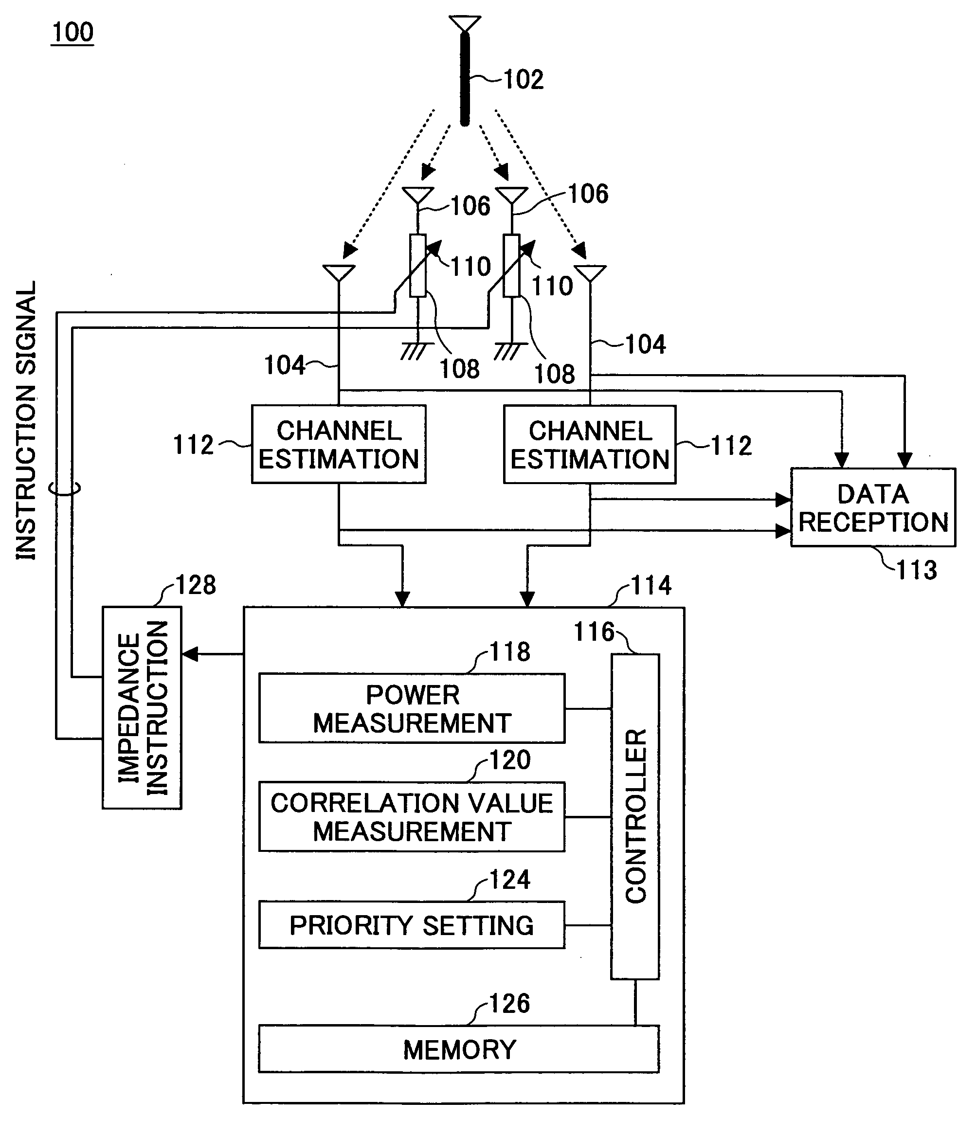
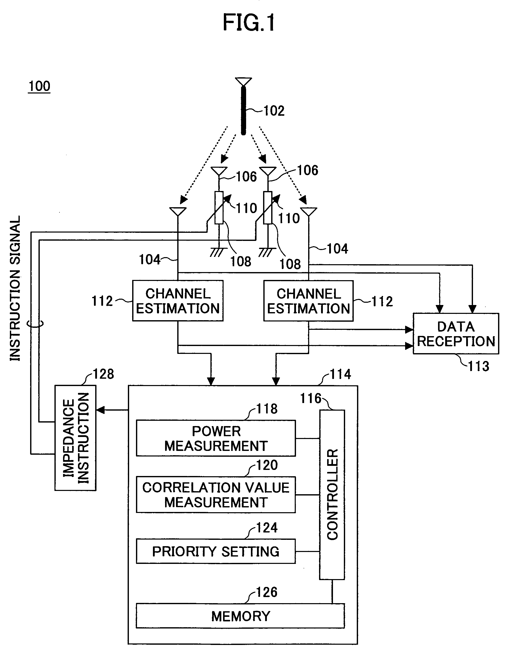
FIG. 1 shows a functional block diagram of a radio receiver according to one embodiment of the present invention. In FIG. 1, among parts / components of the radio receiver, functional blocks particularly relating to the present invention are shown. The radio receiver 100 includes a plurality of antenna elements 104 and 106 for receiving a radio signal transmitted from a transmission antenna 102 of a radio transmitter. For the purpose of simplification, the transmission antenna 102 is expressed as a single element. However, it is also possible to receive signals transmitted from a plurality of antenna elements. In FIG. 1, as the plurality of antenna elements, two driving antenna elements 104 and two parasitic antenna elements 106 are provided. However, in general, it is possible to provide an arbitrary number of antenna elements. However, in order to perform communication in the MIMO system, at least two driving antenna elements are required.

Each of the parasitic antenna elements 106 ...


PUM


Abstract

A radio receiver includes a plurality of antenna elements for receiving a radio signal from a radio transmitter; a setting part changing an impedance of at least one of the plurality of antenna elements according to an instruction signal; a measuring part measuring a change in throughput in a received signal caused due to the change in the impedance; and an instruction part providing the instruction signal which is changed in response to the measurement result.

Description

BACKGROUND OF THE INVENTION 1. Field of the Invention The present invention generally relates to a radio communication technical field, and, in particular, to a radio receiver, a radio transmitter and impedance control method for performing radio communication with the use of a plurality of antenna elements. 2. Description of the Related Art As a technology especially taking into an attention for such a technical field, a so-called multi-input multi-output (MIMO) communication system is known. This system has been developed for improving transmission rate per capacity, i.e., per frequency (bps / Hz) by preparing a plurality of antenna elements at each of a transmission end and a reception end, and simultaneously transmitting different signals for the respective antenna elements within a common frequency band. The above-mentioned capacity is also called throughput. For example, European Patent Application Publication No. 1233565 and G. J. Foschini, et al., ‘Simplified Processing fo...

Claims


Application Information

Patent Timeline
Patent Type & Authority Applications(United States)
IPC IPC(8): H01Q1/24H01Q3/26H01Q3/44H01Q21/29H04B7/06H04B7/08H04L1/00H04L25/02
CPCH01Q1/246H01Q3/2635H04L25/0202H01Q21/29H04L1/0025H01Q3/44
Inventor FUJII, HIROMASATOMISATO, SHIGERUSUDA, HIROHITO
Owner NTT DOCOMO INC
Why Eureka
Try Eureka