Readout circuit, solid state image pickup device using the same circuit, and camera system using the same
a technology of solid-state image pickup and readout circuit, which is applied in the direction of television system, radio-controlled devices, instruments, etc., can solve the problems of deterioration of s/n ratio, reduced readout gain, and large area of holding capacity b>103/b>, so as to improve the s/n ratio and improve the effect of further capacity division
- Summary
- Abstract
- Description
- Claims
- Application Information
AI Technical Summary
Benefits of technology
Problems solved by technology
Method used
Image
Examples
first example
With reference to FIGS. 1 and 2, the present embodiment will be described.
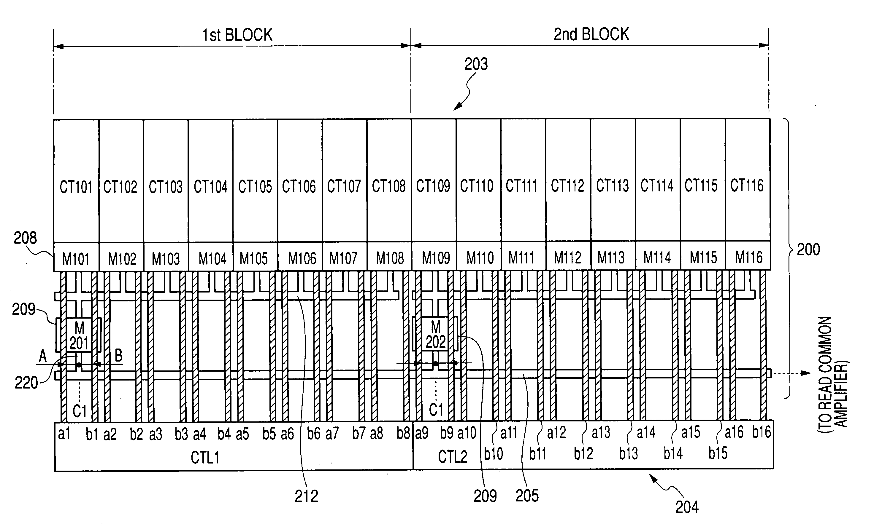
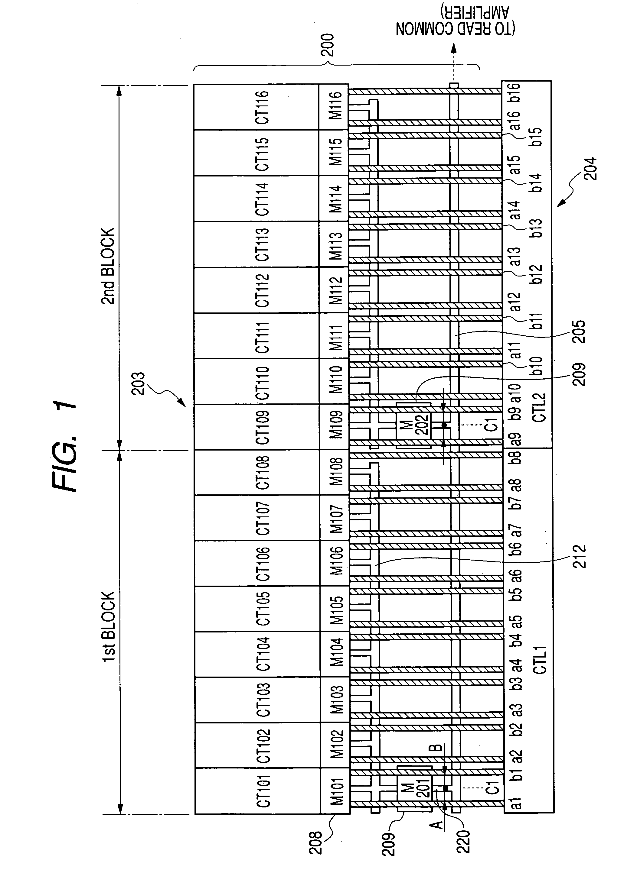
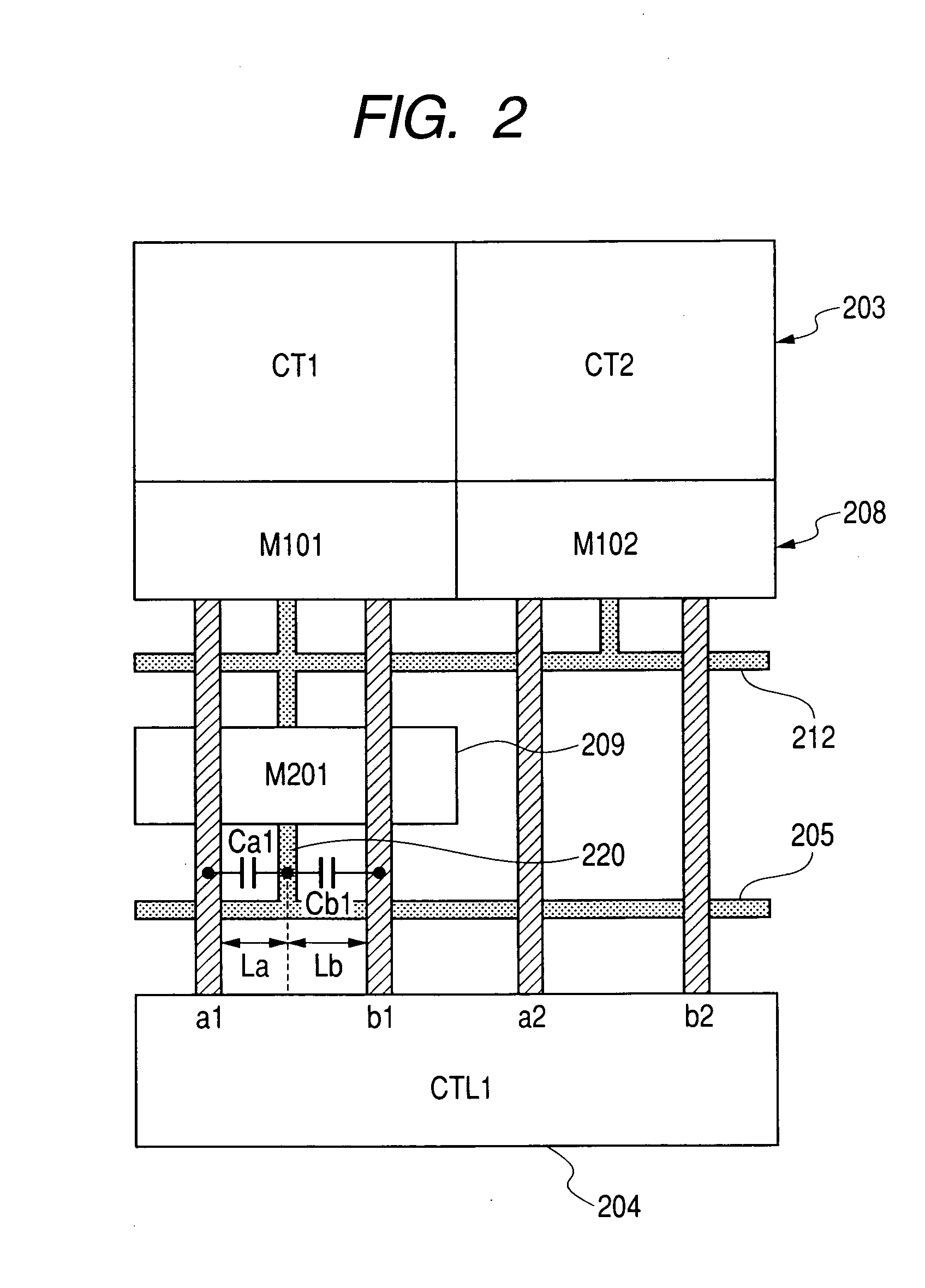
The present example is an example in which eight pieces of holding capacity have been used in a readout circuit obtained by blocking the line memory as one block as in the case of the conventional example shown in the above-described FIGS. 17, 18. FIG. 1 is a layout schematic view showing two blocks (first block B1, second block B2), and FIG. 2 is a view showing one portion (first column, second column from the left column) within one block (first block B1) in detail.
The readout circuit of the solid state image pickup device shown in FIGS. 1 and 2 has a signal readout unit 200 and a control unit 204. Among them, the signal readout unit 200 includes: a line memory 203 to be constructed by a plurality of holding capacity (memory units) CT101 to CT116 for holding signals; first switches M101 to M116 (208) to be connected to each holding capacity CT101 to CT116; first switches M101 to M116 (208) to be connect...
second example
Since the present example is of the structure in which 8 pieces of capacity similar to the first example shown in FIGS. 1, 2 have been converted into blocks, the description will be made with reference to the same Figures. The present example is different from the first example in that each wiring has been arranged in the following wiring layer.
In other words, in the readout circuit according to the present example, the control lines a1 to a16, b1 to b16 (positive signal supply wiring, anti-signal supply wiring) which make a pair, and the outgoing wiring 220 are wired with a first metal, and the first and second common signal lines 212, 205 are wired with a second metal. In other words, wiring 212, 205 extending in the lateral (horizontal) direction in the Figure is wired with the same wiring layer (second metal), and wiring a1 to a16, b1 to b16 and 220 extending in the vertical (perpendicular) direction is wired with the same wiring layer (first metal) respectively.
As a result...
third example
With reference to FIGS. 4, 5, 6 and 7, the present example will be described.
The present example is an example in which 8 pieces of holding capacity have been converted into one block, in which line memories constituting one block are further allocated to first and second line memories which are arranged adjacent alternately for each column and which has been used in the readout circuit for obtaining a difference signal between a signal held in first line memories adjacent to each other and a signal held y the second line memory. This readout circuit is suitable for the two-dimensional solid state image pickup device, the first line memory holds optical signal+noise signal, and the second line memory holds noise signal, and the difference output has been outputted. In this case, the noise signal is reset noise when the OFFSET component of the amplifier or an input terminal thereof is reset in the amplifier type solid state image pickup device called so-called CMOS sensor.
FIG. 4 ...
PUM
 Abstract
Description
Claims
Application Information
 - R&D
- Intellectual Property
- Life Sciences
- Materials
- Tech Scout
- Unparalleled Data Quality
- Higher Quality Content
- 60% Fewer Hallucinations
Browse by: Latest US Patents, China's latest patents, Technical Efficacy Thesaurus, Application Domain, Technology Topic, Popular Technical Reports.
© 2025 PatSnap. All rights reserved.Legal|Privacy policy|Modern Slavery Act Transparency Statement|Sitemap|About US| Contact US: help@patsnap.com


