
Housing component for a device to be ventilated

a technology for housing components and devices, applied in electrical apparatus casings/cabinets/drawers, cooling/ventilation/heating modifications, cabinets, etc., can solve the problems of extreme difficulty in achieving a ratio of open area to total area of perforated openings of more than 80% without endangering mechanical stability and electromagnetic screening action, and achieves the effect of reducing flow resistance and increasing the proportion of effective open area

Inactive Publication Date: 2005-03-10
MINEBEA CO LTD
View PDF12 Cites 9 Cited by
  • Summary
  • Abstract
  • Description
  • Claims
  • Application Information

AI Technical Summary

Benefits of technology

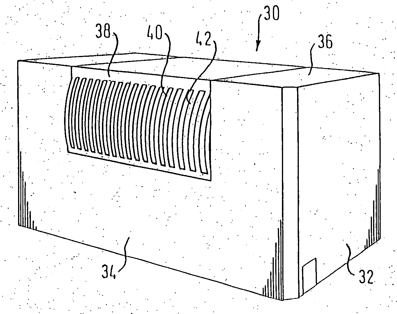
[0006] An air flow through the perforated opening always involves a pressure drop. The invention achieves a minimization of this pressure drop and hence a maximization of the flow rates for the cooling of pieces of electrical and electronic equipment by increasing the open area in relation to the total area of the perforated opening by utilizing the third dimension for the perforated opening. As the lands located between the apertures are staggered or offset against the surface of the wall portion in which the opening is formed, specifically as they protrude from this surface and are bent in the form of a curved segment, elliptical segment, a wave or the like, their effective length increases, whereby the open area between the lands also increases. The total area of the passage apertures is determined by the dimensions of the respective lateral edges of the lands which limit the passage apertures and is, therefore, essentially determined by the linear dimensions of the lands. The base area of the entire perforated opening always remains constant. The design of the perforated ventilation opening according to the invention allows therefore the proportion of the open area in the base area to be increased, resulting in a reduced flow resistance. This allows to achieve a substantially identical air flow and hence a constant cooling action at a reduced fan speed, resulting both in energy savings and in a reduced noise emission. As required, the same fan speed can be used to implement an increased flow rate and hence an improved cooling action.
[0009] The casing component according to the invention is preferably used in metal casings for pieces of electrical and electronic equipment, specifically for power supply units, computers and the like. It is useful in any cases in which electrical or electronic components are to be cooled by means of an air flow, the air flow being generated by a fan or by free convection. The design of the perforated opening according to the invention clearly reduces the flow resistance.

Problems solved by technology

In the perforations generally used today to form ventilation openings in casing walls, it is extremely difficult to achieve a ratio of the open area to the total area of the perforated opening of more than 80% without endangering the mechanical stability and the electromagnetic screening action.

Method used


Image

  • Housing component for a device to be ventilated
  • Housing component for a device to be ventilated
  • Housing component for a device to be ventilated

Examples


Embodiment Construction

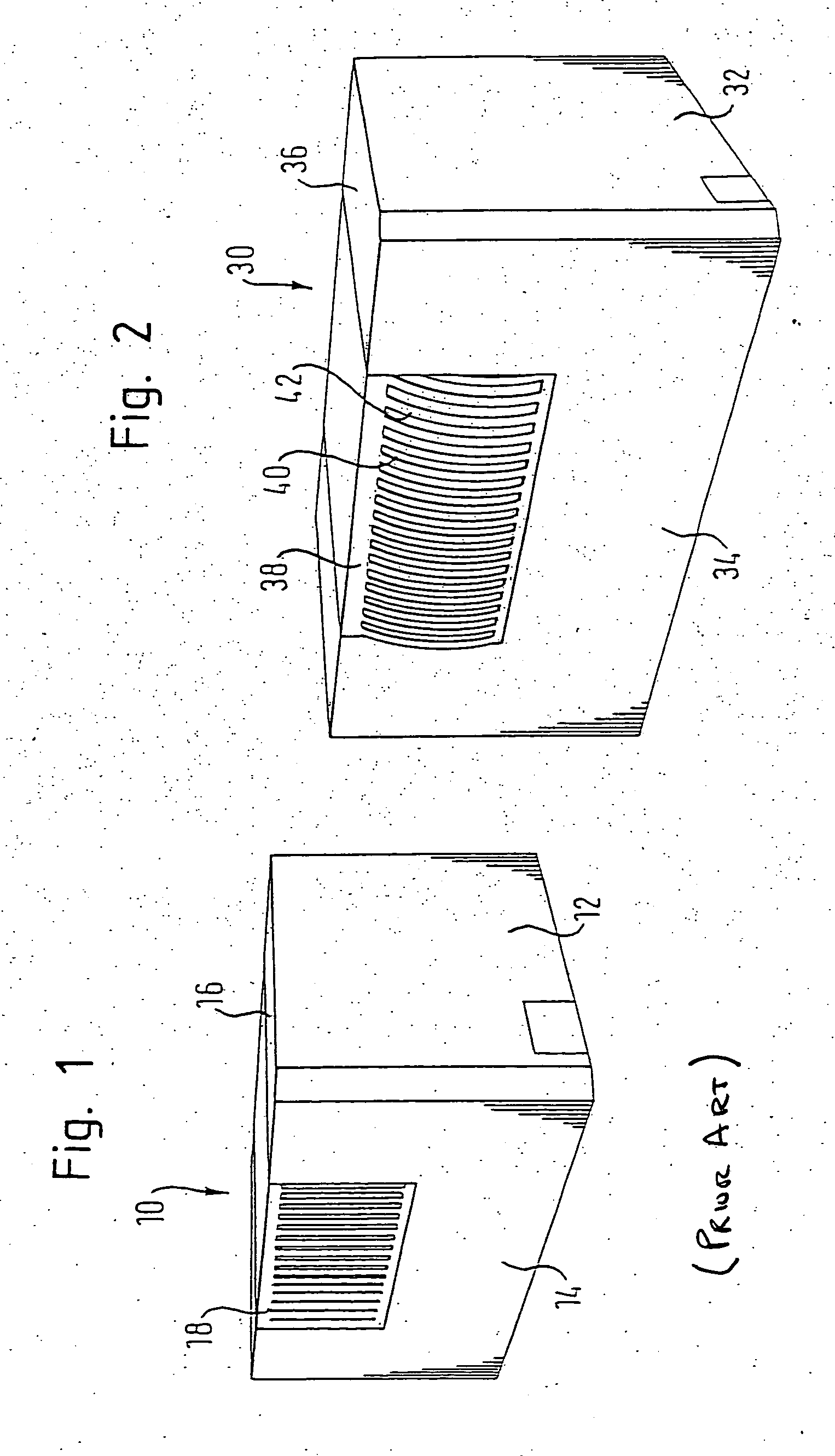
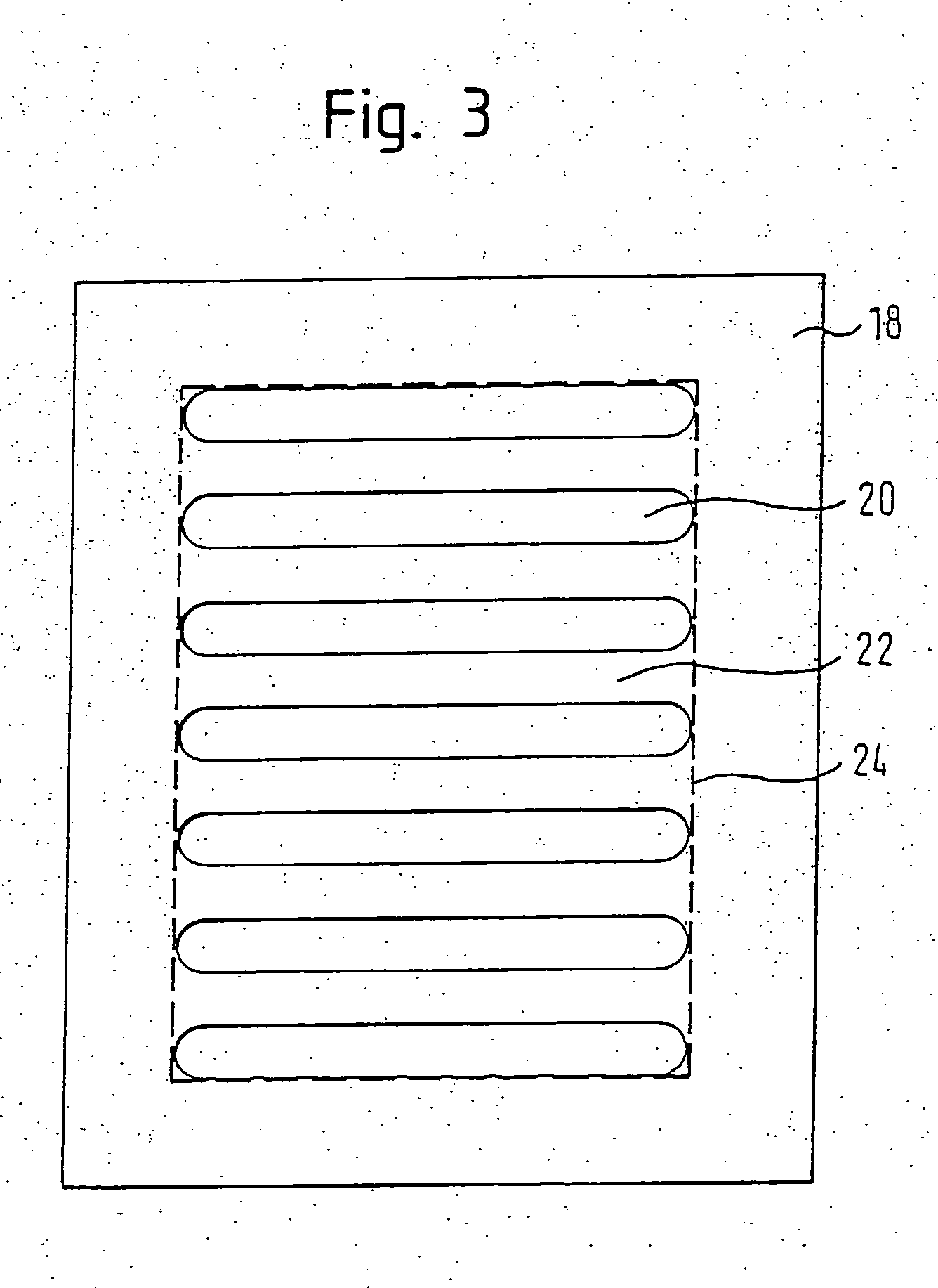
[0016]FIG. 1 schematically depicts an example of a casing 10 for any pieces of electrical and electronic equipment, which has a side panel 12, a back panel 14 (in the front of the drawing) and a cover panel 16. The casing comprises a perforated opening 18 formed as a flat metal plate having alternating elongated slits 20 and lands 22. A schematic top view of such a perforated opening according to the prior art, which has slits 20 and lands 22, is shown in FIG. 3. The lands 22 are also referred to as metal bridges. In FIG. 3, the total area of the perforated region is limited by a line 24. In FIG. 4, which depicts a schematic cross-sectional view of the passage plate 18 of FIG. 3, the open air passage surface limited by the lands 22 is schematically represented by arrows 26.

[0017]FIG. 2 shows a casing 30 for any piece of electrical or electronic equipment which has a side panel 32, a back panel 34 and a cover panel 36 according to the invention. In the back panel 34, a perforated pa...


PUM


Abstract

The invention relates to a housing component for a device to be ventilated, in particular an electrical or electronic device such as a mains piece with a planar wall section and a perforated aperture in the wall section. The aperture comprises several openings and webs between the openings. The webs are at least partly displaced relative to the surface of the wall section and preferably curved and thus elongated such that the total area of the openings defined by the webs is increased. The flow resistance of the perforated aperture, which is determined by the proportion of free surface to the base area of the aperture, is thus reduced.

Description

FIELD OF THE INVENTION [0001] The present invention refers to a casing component for a piece of equipment to be ventilated which comprises a flat wall portion and a perforated opening in the wall portion which includes multiple apertures and lands located between the apertures. DESCRIPTION OF THE PRIOR ART [0002] Numerous pieces of electrical and electronic equipment such as power supply units of all types, computers and other electronic devices must be cooled in many applications, fans being often used in the pieces of equipment to support cooling but in some devices cooling may also occur due to free convection. [0003] To ensure a sufficient cooling of such equipment, the casings thereof generally include at least one perforated opening in one casing wall which comprises multiple apertures and lands located between the apertures to allow an air flow through the casing. Although an optimum ventilation of the casing could be achieved by a completely open opening, grille-like ventila...

Claims


Application Information

Patent Timeline
IPC IPC(8): H05K7/20H05K5/02
CPCH05K5/0213
Inventor BREIER, ANTON
Owner MINEBEA CO LTD
Learn More