
Digital copying machine and a digital copying machine system

a copying machine and digital technology, applied in the direction of digital computers, digital output to print units, instruments, etc., can solve the problems of difficulty in attaching or detaching the units to or from the machine, difference between times, and inability for users to easily attach the units to the machine, so as to achieve a high degree of flexibility and high performance

Inactive Publication Date: 2005-03-10
URABE AKIO +2
View PDF12 Cites 9 Cited by
  • Summary
  • Abstract
  • Description
  • Claims
  • Application Information

AI Technical Summary

Benefits of technology

"The present invention provides a digital copying machine and system with higher flexibility using a high performance serial interface as an inner interface. The machine has a scanner control unit, drawing control unit, and main control unit connected by a high performance serial interface. The machine can be connected to various optional units such as a sorter, paper tray, ADF, and more using the same high performance serial interfaces. The main control unit controls the high performance serial interfaces and can transfer data to external devices using a high performance serial interface and bridge. The invention also allows for parallel operation of at least two machines connected by a bridge and ensures data transfer when one machine fails. The use of a high performance serial interface as an external interface for the bridge further enhances the flexibility of the system."

Problems solved by technology

However, the conventional digital copying machine has prepared a different type of interface for each essential unit or option unit, which does not allow the user to easily attach the units to the machine.
Thus, the attachment or detachment of the units to or from the machine is not easily carried out.
When a high-speed signal is transmitted through a plurality of signal lines, in association with an increase in the number of lines, a difference between times, at which the signal arrives in each of the signal lines, becomes a more serious problem (problems such as racing or skew).
Based on the transmission, there are such problems: 1) the transmission clock rate can not be increased so much, and 2) the signal line can not be made so long.
The above mentioned first problem becomes an urgent matter because the digital copying machine has recently been speeded up.

Method used


Image

  • Digital copying machine and a digital copying machine system
  • Digital copying machine and a digital copying machine system
  • Digital copying machine and a digital copying machine system

Examples


first embodiment

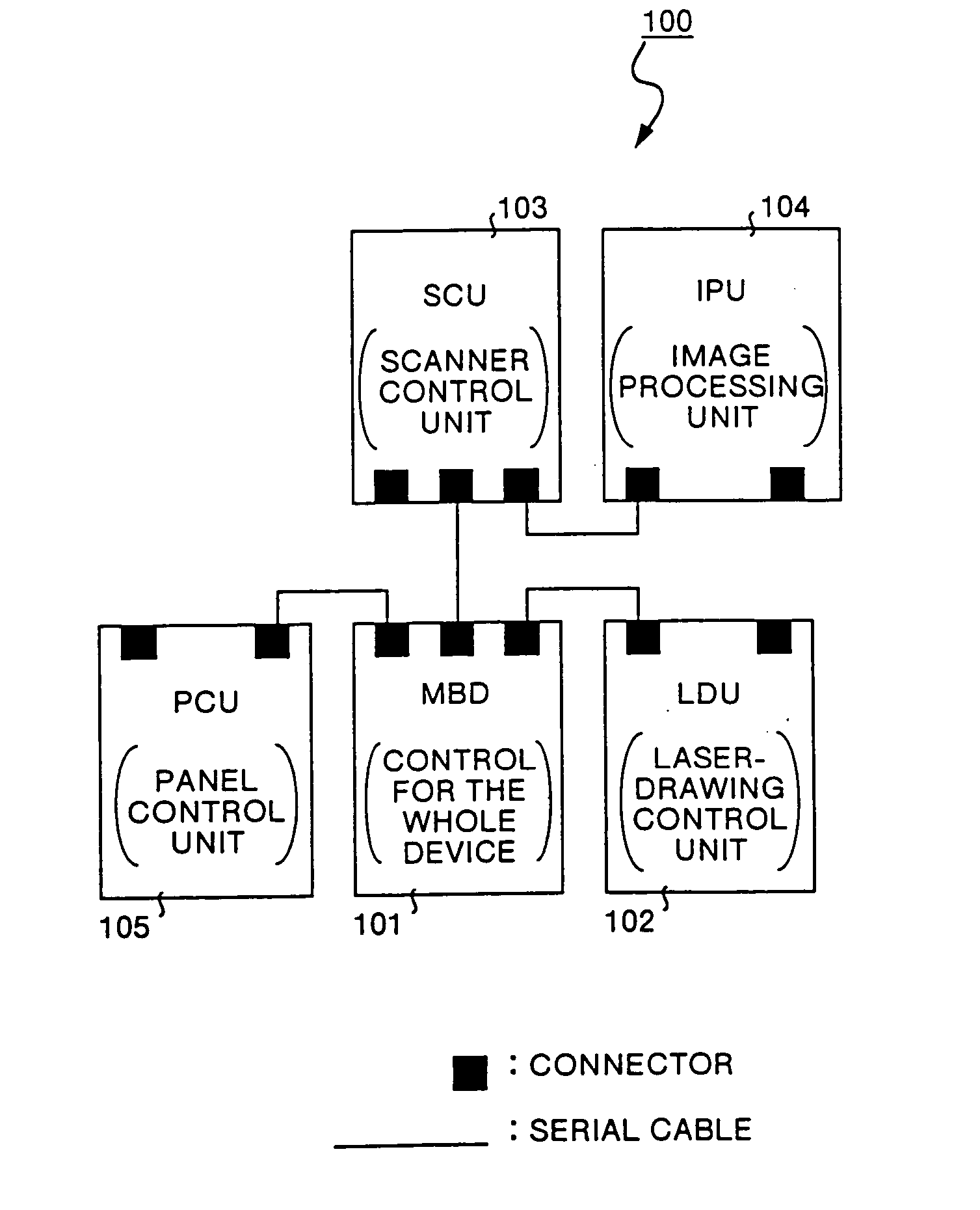
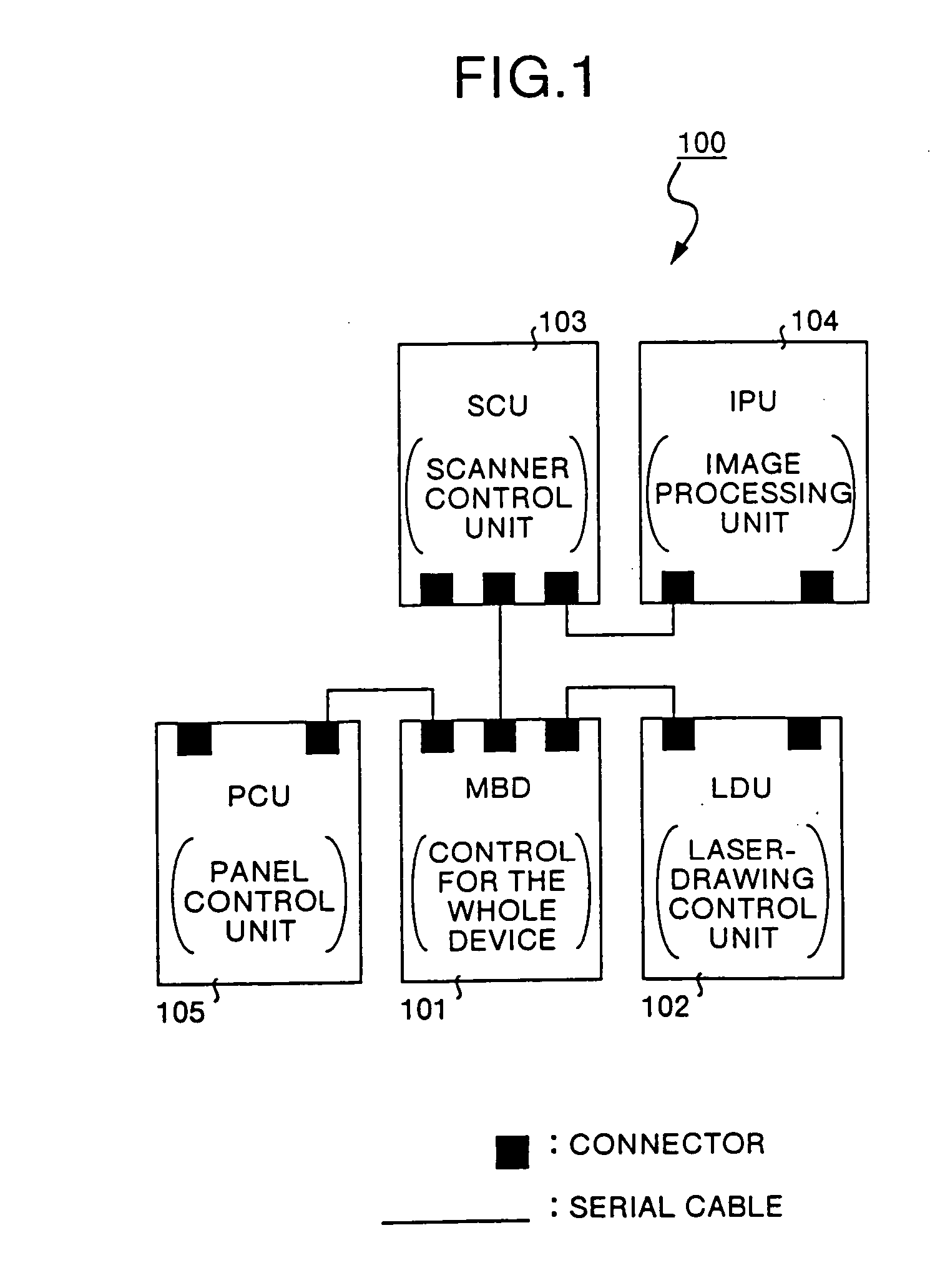
[0052]FIG. 1 shows a schematic configuration of a digital copying machine 100 according to a Referring to the digital copying machine shown in FIG. 1, the case, where an IEEE 1394 standard interface as a high performance serial interface is used as an inner interface, is explained below.

[0053] In FIG. 1, reference numeral 101 represents a MBD (motherboard) that controls the overall device of the digital copying machine 100. Reference numeral 102 represents an LDU (laser-drawing control unit) that controls a drawing laser with which an image is drawn onto a photoconductive drum. Reference numeral 103 represents an SCU (scanner control unit) that controls a scanner, 104 an IPTU (image processing unit) that performs digital image processing, and 105 a PCU (panel control unit) that controls a control panel through which a user gives an instruction for an operation. Each of the units 101 to 105 has an IEEE 1394-compatible high performance serial interface.

[0054] As shown in FIG. 1, the...

second embodiment

[0079]FIG. 8 shows a schematic configuration of a digital copying machine according to the The digital copying machine shown in FIG. 8 represents a configuration in which the number of units in the four-drum digital copying machine is kept to a minimum. Referring to the digital copying machine shown in FIG. 8, the case where the IEEE 1394 standard interface as a high performance serial interface is used as an inner interface is explained below.

[0080] In FIG. 8, reference numeral 101 represents an MBD (motherboard) that controls the overall machine. Reference numeral 102A represents an LDU 1 (laser-drawing control unit) that controls a drawing laser (for Bk) with which an image is drawn onto a photoconductive drum, and 102B an LDU 2 (laser-drawing control unit) that controls a drawing laser (for C) with which an image is drawn onto the photoconductive drum. Reference numeral 102C represents an LDU 3 (laser-drawing control unit) that controls a drawing laser (for M) with which an ima...

third embodiment

[0091] Although, in the third embodiment, the case where the IEEE 1394 standard interface is used as a high performance serial interface has been explained, the present invention is not limited to this interface. Thus the USB may be used as a high performance serial interface.


PUM


Abstract

The digital copying machine has a MBD that controls the overall device of the digital copying machine. The machine also has an LDU that controls a drawing laser with which an image is drawn onto a photoconductive drum, an SCU that controls a scanner, and a PCU that controls a control panel through which a user gives an instruction for an operation. These units are directly connected to the MBD by serial cables via their respective high performance serial interfaces.

Description

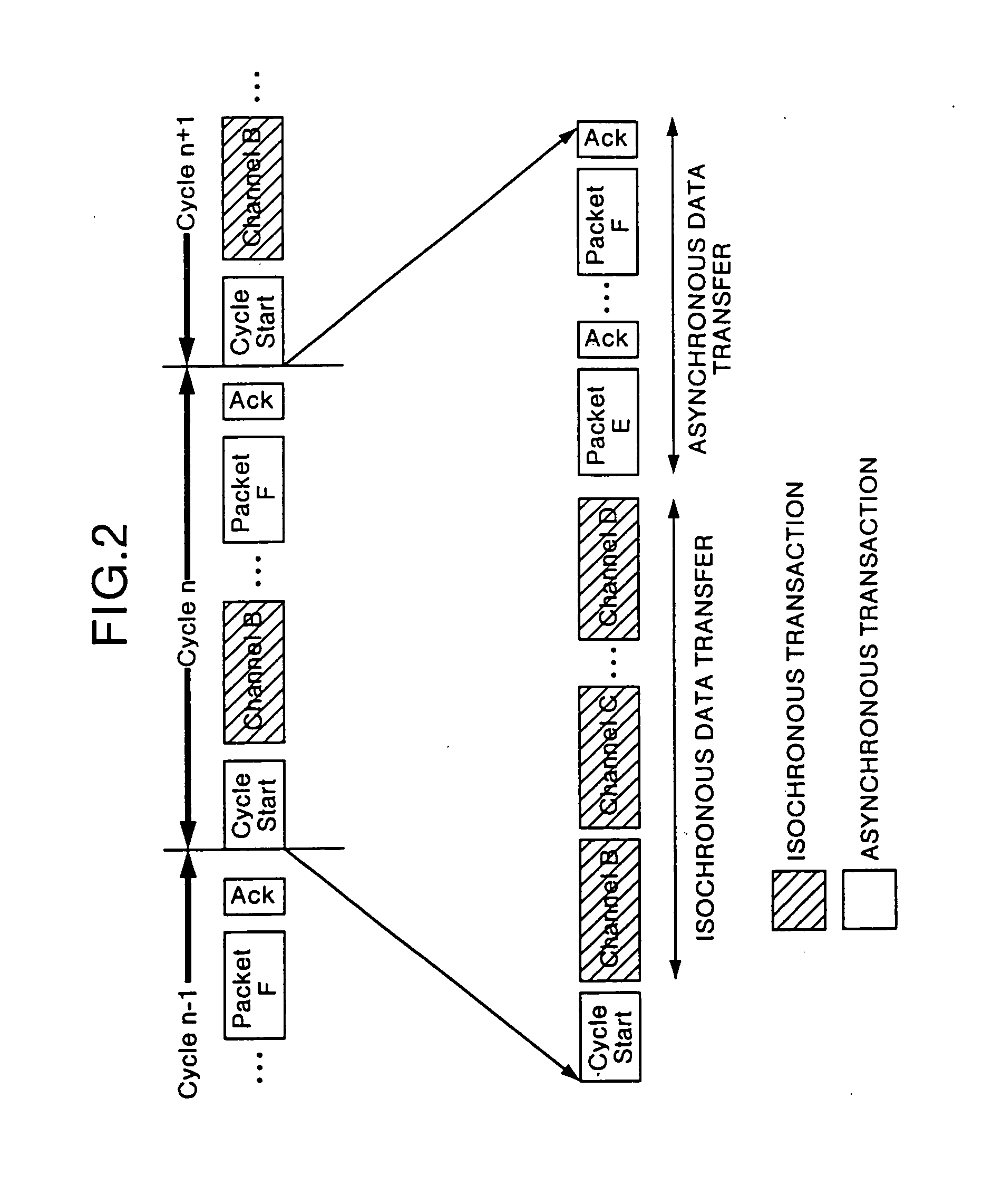
FIELD OF THE INVENTION [0001] The present invention relates to a digital copying machine and a digital copying machine system. More particularly, this invention relates to a digital copying machine and a digital copying machine system in which a high performance serial interface is used for an inner interface. BACKGROUND OF THE INVENTION [0002] The technology of a high performance serial interface has been coming into wide use in recent years. For example, employment of a high performance serial interface such as a USB (Universal Serial Bus) and a bus (henceforth, “IEEE 1394 bus”) defined in the IEEE standard for a High Performance Serial Bus (IEEE 1394-1995) [1] is recommended or obliged in the standard on PC 98[2]. [0003] The IEEE 1394 bus supports up to 400 Mbps, and it is planed to be further speeded up to 800 Mbps or 1.6 Gbps. The IEEE 1394 bus prepares an isochronous transfer mode in addition to an asynchronous transfer mode. This isochronous transfer mode has a function of pr...

Claims


Application Information

Patent Timeline
Patent Type & Authority Applications(United States)
IPC IPC(8): G06F13/38G06F15/00G06F3/12H04N1/00H04N1/04H04N1/32
CPCH04N1/0083H04N1/32523H04N2201/0091H04N1/32561H04N1/32593H04N1/32545
Inventor URABE, AKIOWATANABE, HIDEYUKIKANAYA, MITSUHISA
Owner URABE AKIO
Learn More