
Linear voltage tracking amplifier for negative supply slew rate control

a linear voltage tracking and negative supply technology, applied in the direction of electronic switching, pulse technique, electric analogue stores, etc., can solve the problems of affecting the operation of the system processor, and triggering unwanted system resets, etc., to achieve the effect of reducing costs

Active Publication Date: 2005-03-10
TEXAS INSTR INC
View PDF6 Cites 18 Cited by
  • Summary
  • Abstract
  • Description
  • Claims
  • Application Information

AI Technical Summary

Benefits of technology

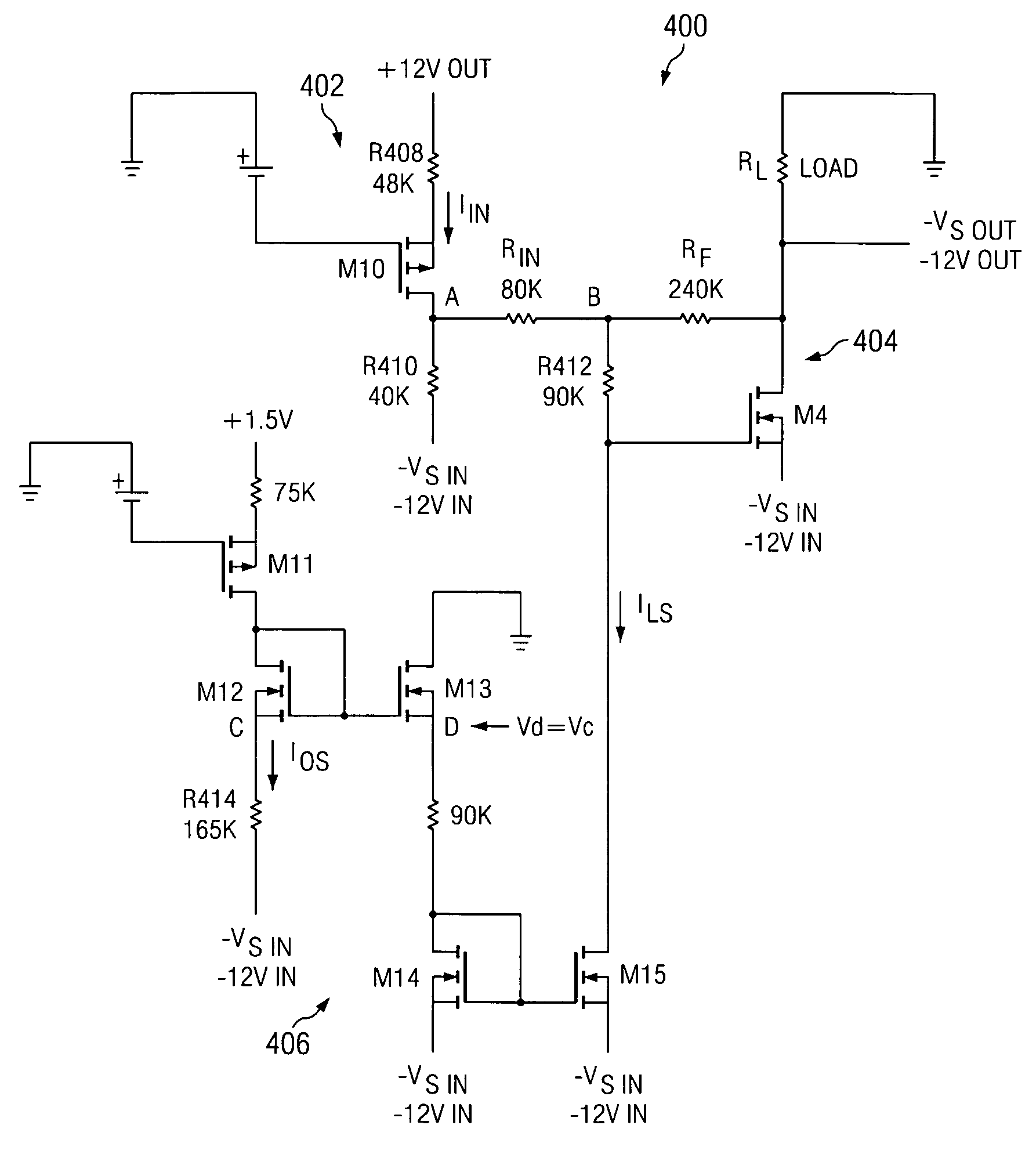
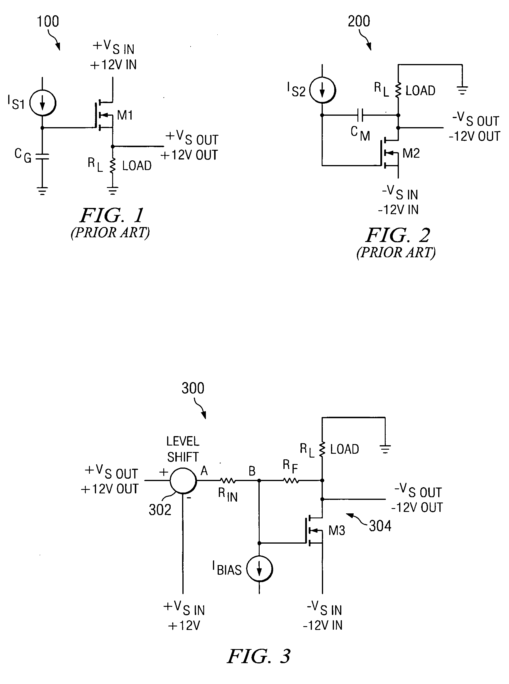
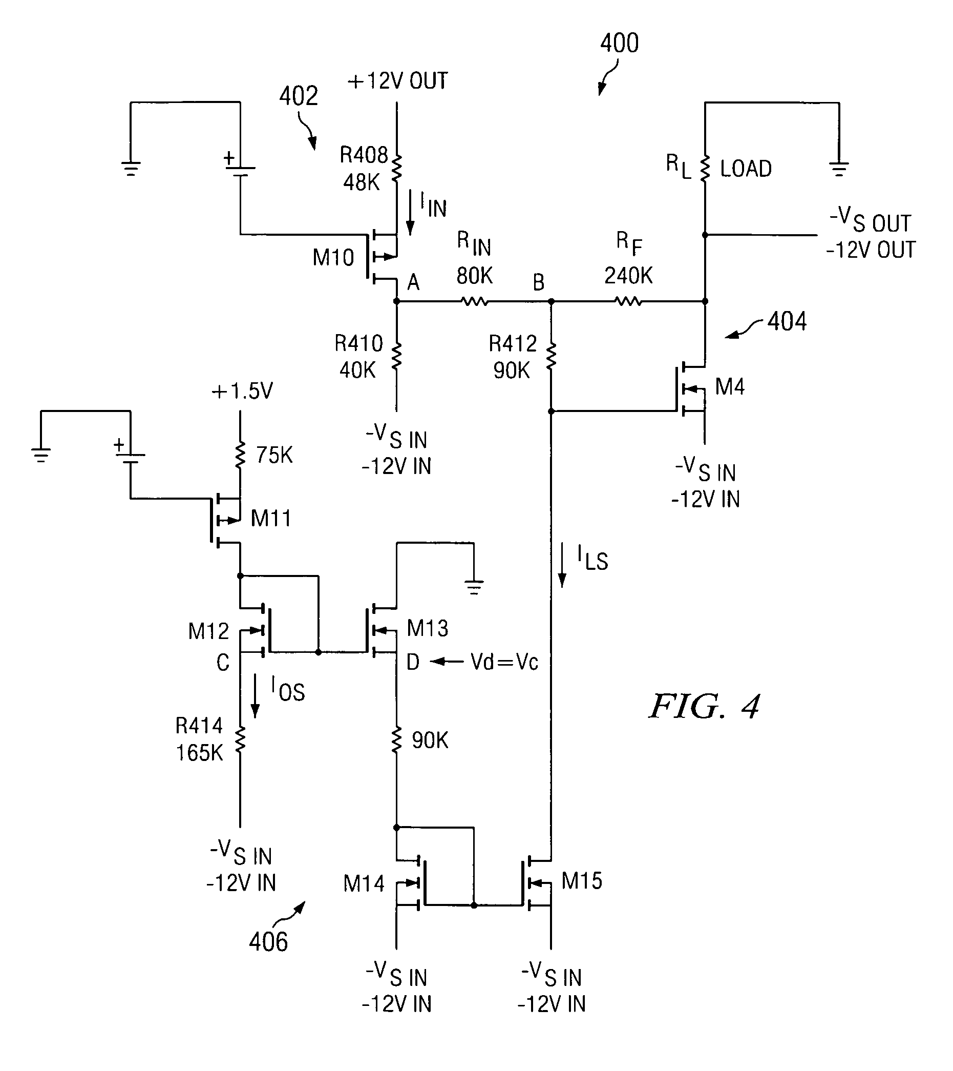
[0009] In accordance with the present invention, circuitry is provided for controlling the slew rate of a negative output supply that requires neither an external capacitor nor a PMOS FET and therefore has reduced cost. Benefits of the presently disclosed slew rate control circuitry are achieved by employing an NMOS FET in a closed loop circuit configuration, in which the slew rate of the negative output supply linearly tracks the slew rate of a master positive output supply.

Problems solved by technology

Such slew rate control of the mother PC card power supply is necessary because excessive in-rush current can (1) adversely affect the operation of the switched power supply, (2) trigger unwanted system resets, and / or (3) disrupt system processor operation.
For example, the source-follower requires a charging capacitor, which can be bulky and expensive.
Further, when controlling the slew rate of a negative output supply voltage, the source-follower requires a PMOS FET, which can also be an expensive circuit component.
However, this alternative circuit configuration also has drawbacks due at least in part to the bulky and expensive Miller capacitor.

Method used


Image

  • Linear voltage tracking amplifier for negative supply slew rate control
  • Linear voltage tracking amplifier for negative supply slew rate control
  • Linear voltage tracking amplifier for negative supply slew rate control

Examples


Embodiment Construction

[0020] U.S. Provisional Patent Application No. 60 / 501,006 filed Sep. 8, 2003 Attorney Docket No. TI-36859 FOR NEGATIVE SUPPLY SLEW RATE CONTROL is incorporated herein by reference.

[0021] Circuitry is disclosed for controlling the slew rate of a negative output supply. The presently disclosed slew rate control circuitry includes a closed loop circuit configuration that allows the slew rate of the negative output supply to linearly track the slew rate of a master positive output supply.

[0022]FIG. 1 depicts conventional circuitry 100 for controlling the slew rate of a positive output supply. As shown in FIG. 1, the conventional slew rate control circuitry 100 employs a source-follower circuit configuration including an NMOS Field Effect Transistor (FET) M1, a constant current source IS1, a gate capacitor Cg, and a load resistor RL. The capacitor Cg is connected between the gate of the NMOS transistor M1 and ground, a constant positive input supply voltage +VSin (e.g., +VSin=+12 volts...


PUM


Abstract

Circuitry is provided for controlling the slew rate of a negative output supply. The slew rate control circuitry includes an NMOS FET, a feedback resistor connected across the drain and the gate of the NMOS FET, an input resistor connected to the gate of the NMOS FET, level shifting circuitry connected between a positive output supply voltage and the input resistor, and a bias current source connected to the gate of the NMOS FET. A negative input supply voltage is connected to the source of the NMOS FET, and the negative output supply voltage is provided across a load connected to the drain of the NMOS FET. As the positive supply voltage ramps up from 0 to +VS, the level shifter provides a voltage to the input resistor that ramps up from −VS to 0 volts. Further, the drain voltage of the NMOS FET ramps down from 0 to −VS, thereby providing a negative output supply voltage −VS with a slew rate that linearly tracks the slew rate of the master positive output supply.

Description

CROSS REFERENCE TO RELATED APPLICATIONS [0001] This application claims priority of U.S. Provisional Patent Application No. 60 / 501,006 filed Sep. 8, 2003 entitled LINEAR VOLTAGE TRACKING AMPLIFIER FOR NEGATIVE SUPPLY SLEW RATE CONTROL.STATEMENT REGARDING FEDERALLY SPONSORED RESEARCH OR DEVELOPMENT [0002] N / A BACKGROUND OF THE INVENTION [0003] The present application relates generally to slew rate control circuitry, and more specifically to circuitry for controlling the slew rate of switched power supplies. [0004] Slew rate control circuitry is frequently employed in conjunction with switched power supplies. For example, the slew rate of a switched power supply on a mother printed circuit (PC) card is often controlled to limit the in-rush current charging bulk decoupling capacitors on one or more daughter PC cards. Such slew rate control of the mother PC card power supply is necessary because excessive in-rush current can (1) adversely affect the operation of the switched power supply...

Claims


Application Information

Patent Timeline
IPC IPC(8): H03F1/30H03K5/12
CPCH03F1/305
Inventor JACOBS, KARL H.NEIDORFF, ROBERT
Owner TEXAS INSTR INC
Learn More