
Heat exchangers with novel ball joints and assemblies and processes using such heat exchangers

Inactive Publication Date: 2005-03-10
HEAT TRANSFER INT
View PDF17 Cites 11 Cited by
  • Summary
  • Abstract
  • Description
  • Claims
  • Application Information

AI Technical Summary

Benefits of technology

[0015] The invention disclosed and claimed herein deals with heat exchangers with novel ball joints and assemblies and processes using such heat exchangers, and systems comprising several heat exchangers or systems comprising heat exchangers that are fabricated such that they provide more efficient heat exchanges then has been possible heretofore. The invention dis

Problems solved by technology

These metal heat exchangers are subject to deterioration from chemically corrosive or abrasive particles and further, they are subject to wide latitudes of expansion under operating conditions.
The particulates in the waste fumes have a tendency to plug the matrix after a period of time thereby decreasing the efficiency and, in some instances, creating a fire hazard.
Systems employing metal components to seal ceramics are subject to leakage problems since metal has a different rate of expansion than ceramic.
In addition, the metallic components are still subject to deterioration under the above-mentioned adverse conditions in which these types of heat exchangers may be used.
Also, in the likely event of power failure, the metallic springs will lose resiliency and will fail when air side cooling stops.
Thus, the heat exchangers are normally stacked or otherwise fastened together to increase the operating flow length of both the ambient air and the waste gas and the flow of the ambient air between the plenums and tubes creates a pressure loss within the system.
These pressure losses also make it difficult to operate at higher pressures, and consequently, the heat exchangers of the prior art are not operated at the high pressu

Method used


Image

  • Heat exchangers with novel ball joints and assemblies and processes using such heat exchangers
  • Heat exchangers with novel ball joints and assemblies and processes using such heat exchangers
  • Heat exchangers with novel ball joints and assemblies and processes using such heat exchangers

Examples


Example

DETAILED DESCRIPTION OF THE DRAWINGS

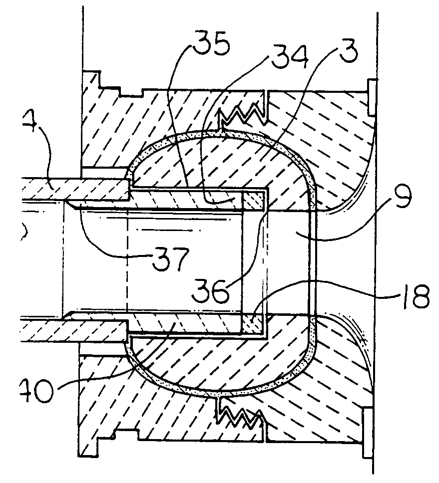
[0068] Turning now to the Figures, and with regard to FIG. 5A, there is shown an enlarged cross-sectional view of a slidable ball joint 1 of this invention. The slidable ball joint assembly comprises in combination, a spherical body 3 and a ceramic tube 4.

[0069] The spherical body 3 has an outer surface 5 and an inner surface 6 and it has a near side 7 and a tube side 8. The near side 7 and the tube side 8 each have a center point shown by the line D-D. Each of the near side 7 and the tube side 8 have a truncated face to form a flat surface on them.

[0070] The spherical body 3 has an opening 9 of predetermined length, the predetermination being based on the amount of the reduced diameter end of the ceramic tube 4 that is required to be inserted into the opening in order that the spherical ball 3 can stabilize and support the ceramic tube 4.

[0071] The opening 9 in the spherical body 3 traverses the entire length of the spherical body 3 such that...


PUM


Abstract

What is disclosed herein deals with low to medium pressure, high temperature, all ceramic, air-to-air, indirect heat exchangers, novel ball joints, high load-bearing ceramic tube sheets, and tube seal extenders for ceramic tubes that are useful in such heat exchangers. Also disclosed are new and novel systems used in new and novel industrial processes such as chemical processing, sludge destruction and the production of particulates such as, for example, carbon black. Systems utilizing several heat exchangers are also disclosed.

Description

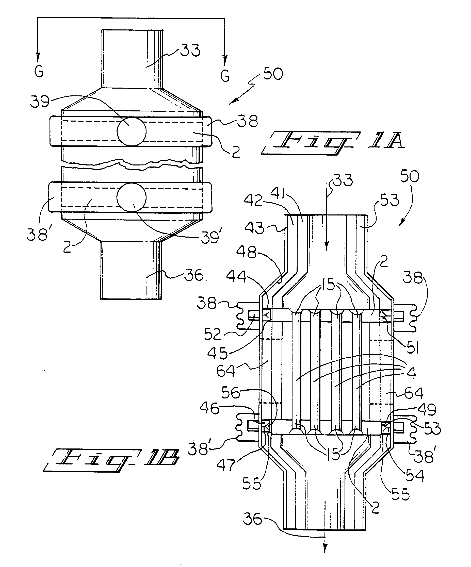
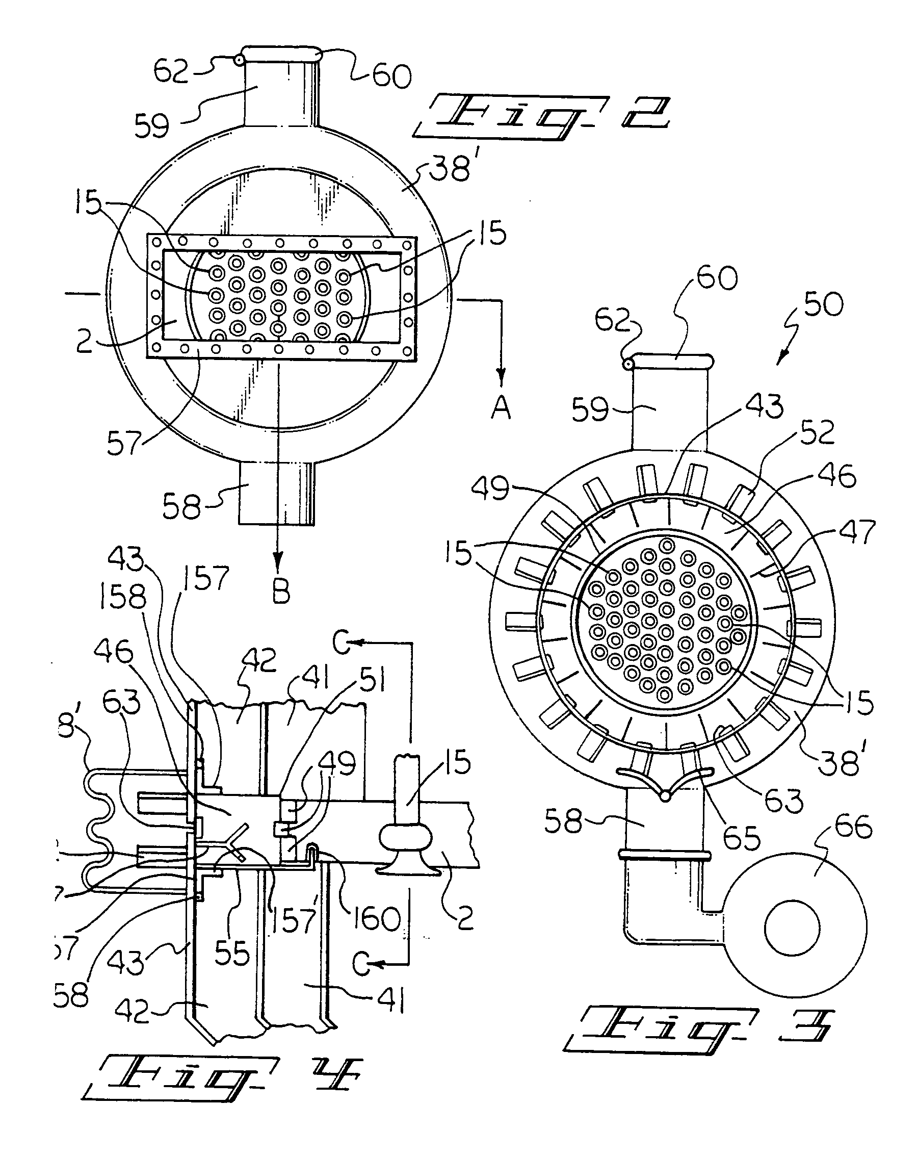
[0001] The invention disclosed and claimed herein deals with low to medium pressure, high temperature, all ceramic, air-to-air, indirect heat exchangers, novel ball joints, high load-bearing ceramic tube sheets, and tube seal extenders for ceramic tubes that are useful in such heat exchangers. Also disclosed are new and novel systems used in processes that are used in the heat exchangers of this invention. The inventor herein also contemplates systems utilizing several heat exchangers or systems comprising heat exchangers within the scope of this invention. [0002] The heat exchangers of this invention are not merely modified standard heat exchangers that are in use today, but are new and novel heat exchangers that have outstanding efficiencies in operation, among other valuable benefits. In many industrial processes, the heat exchangers of this invention reduce substantially, the combustion products going out the stack that means that from an environmental perspective, there is less...

Claims


Application Information

Patent Timeline
IPC IPC(8): F28F9/02F28F9/06F28F19/00F28F21/04
CPCF28F9/0239F28F9/06F28F2265/26F28F21/04F28F19/002
Inventor GRAHAM, ROBERT G.
Owner HEAT TRANSFER INT
Learn More