Lithographically built optical structures

Inactive Publication Date: 2005-03-03
STATE OF ISRAEL - SOREQ NUCLEAR RES CENT
View PDF4 Cites 13 Cited by
  • Summary
  • Abstract
  • Description
  • Claims
  • Application Information

AI Technical Summary

Benefits of technology

[0017] In an embodiment of the present invention, two half waveguides are formed and bonded together. The half waveguides themselves may be created using a lithographic process on, for example, a glass or a polymeric substrate. Being a half waveguide, the core is open to the air and therefore complex treatments may be performed. Using the lithographic process enables coupling light inside such a wav

Problems solved by technology

Being a half waveguide, the core is open to the air and therefore complex treatments may be performed.

Method used


Image

  • Lithographically built optical structures
  • Lithographically built optical structures
  • Lithographically built optical structures

Examples


Embodiment Construction

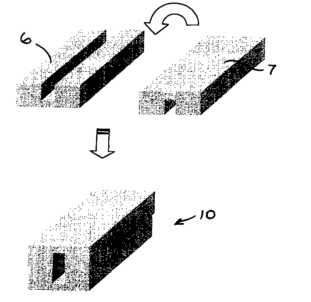
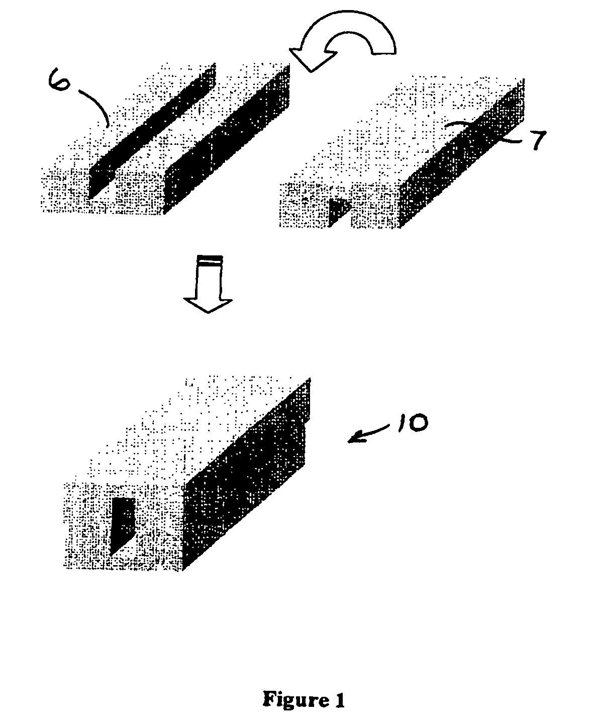
[0039] Reference is now made to FIG. 1, which illustrates a two-step fabrication of a hollow waveguide or optical fiber, in accordance with an embodiment of the present invention.

[0040] Two half-waveguides 6 and 7 may be manufactured by a lithographic process as is described hereinbelow. The two half-waveguides 5 and 7 may then be attached to one another to form a complete waveguide 10, such as by bonding or deposition, for example, as is described hereinbelow.

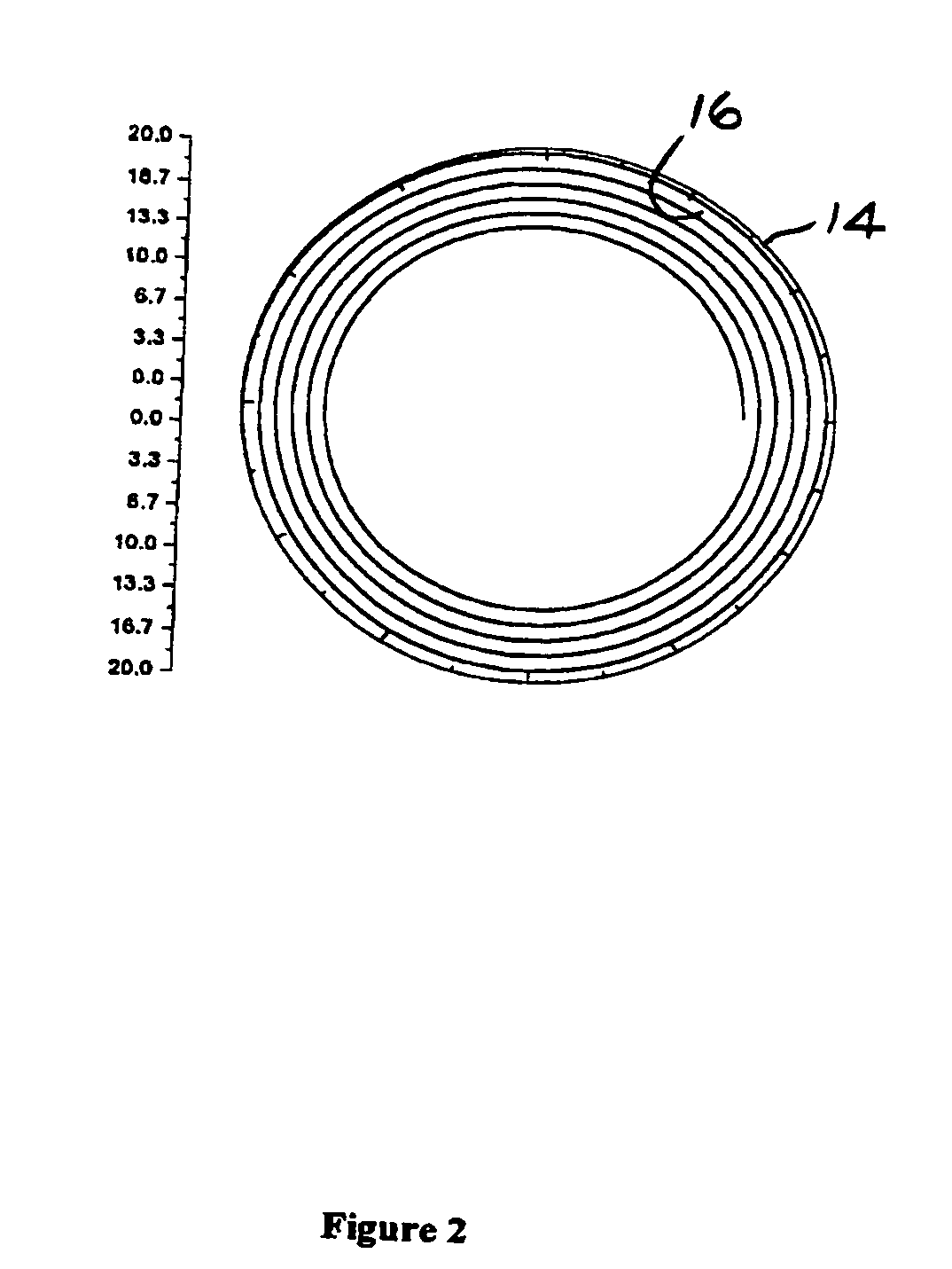
[0041] Referring to FIG. 2, a thin photoresist layer 14 may be deposited, such as but not limited to, by means of spin-coating, on a polymeric substrate 16. The substrate 16 may be illuminated through a mask (not shown) in order to etch a waveguide profile. A pattern can be also directly written using a focused laser. A long deposition chamber may be used for linear geometry, that is, to deposit layer 14 on a relatively long substrate 16. Alternatively, in order to save room in the deposition chamber, the mask may have a spi...


PUM


Abstract

Optical apparatus including an optical waveguide including a hollow core formed lithographically. The optical waveguide may include a cladding with a reflective surface deposited thereon. The reflective surface may include a metallic coating, a multilayer dielectric coating, a multi-dimensional photonic crystal, and / or may be doped with a lasing material. The multilayer dielectric coating may include only dielectric layers or a combination of dielectric and metal layers.

Description

FIELD OF THE INVENTION [0001] The present invention relates generally to fabricating optical fibers and waveguides, such as but not limited to, laser fibers and photonic crystal fibers, and particularly to fabricating optical fibers and waveguides with lithographic techniques. BACKGROUND OF THE INVENTION [0002] Optical fibers often have a circular section while waveguides often have a rectangular section. One of the main reasons for this is that optical fibers are manufactured by melting a preform, and the circular geometry is most adapted for this manufacturing process. Manufacturing optical fibers by melting a preform is suitable for making long fibers, especially for telecommunications. [0003] However, there are more and more cases where fibers are not sought for the long distance transport (“extra-muros”), but rather for short distances (“intra-muros”, up to a few meters). In that case, the circular section is not mandatory. However, very special properties are required from suc...

Claims


Application Information

Patent Timeline
IPC IPC(8): G02B6/00
CPCG02B6/00
Inventor SFEZ, BRUNO
Owner STATE OF ISRAEL - SOREQ NUCLEAR RES CENT
Why Eureka
Try Eureka