Protector
a technology of protection device and protective shield, which is applied in the direction of insulated conductor, electrical apparatus casing/cabinet/drawer, cables, etc., can solve the problems of parts deterioration, and achieve the effect of easy production
- Summary
- Abstract
- Description
- Claims
- Application Information
AI Technical Summary
Benefits of technology
Problems solved by technology
Method used
Image

Examples
first embodiment
[0040] [First Embodiment]
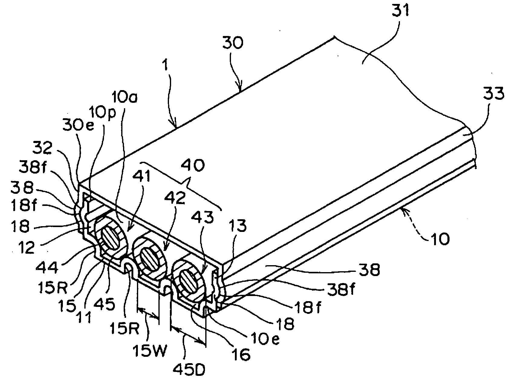
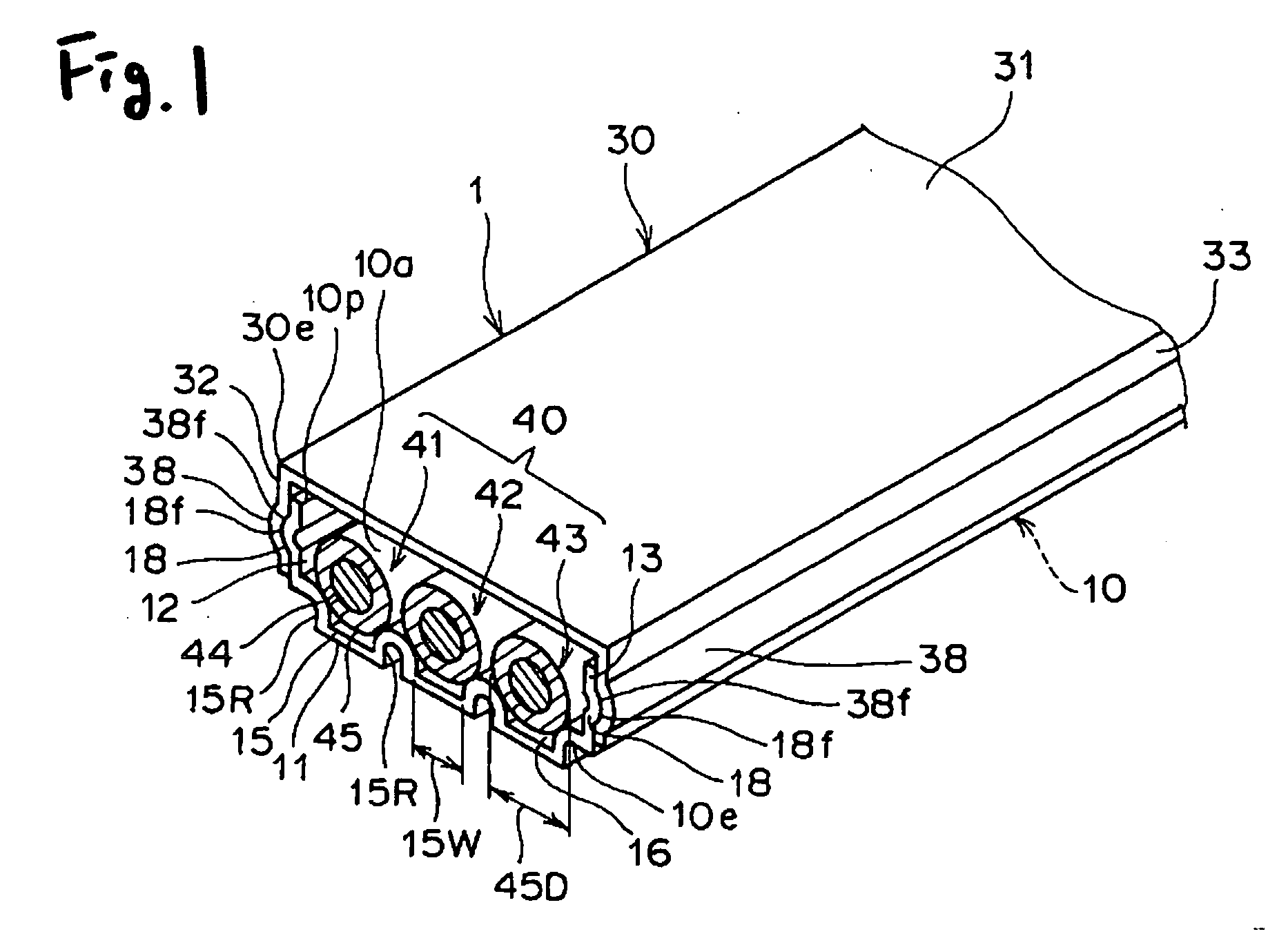
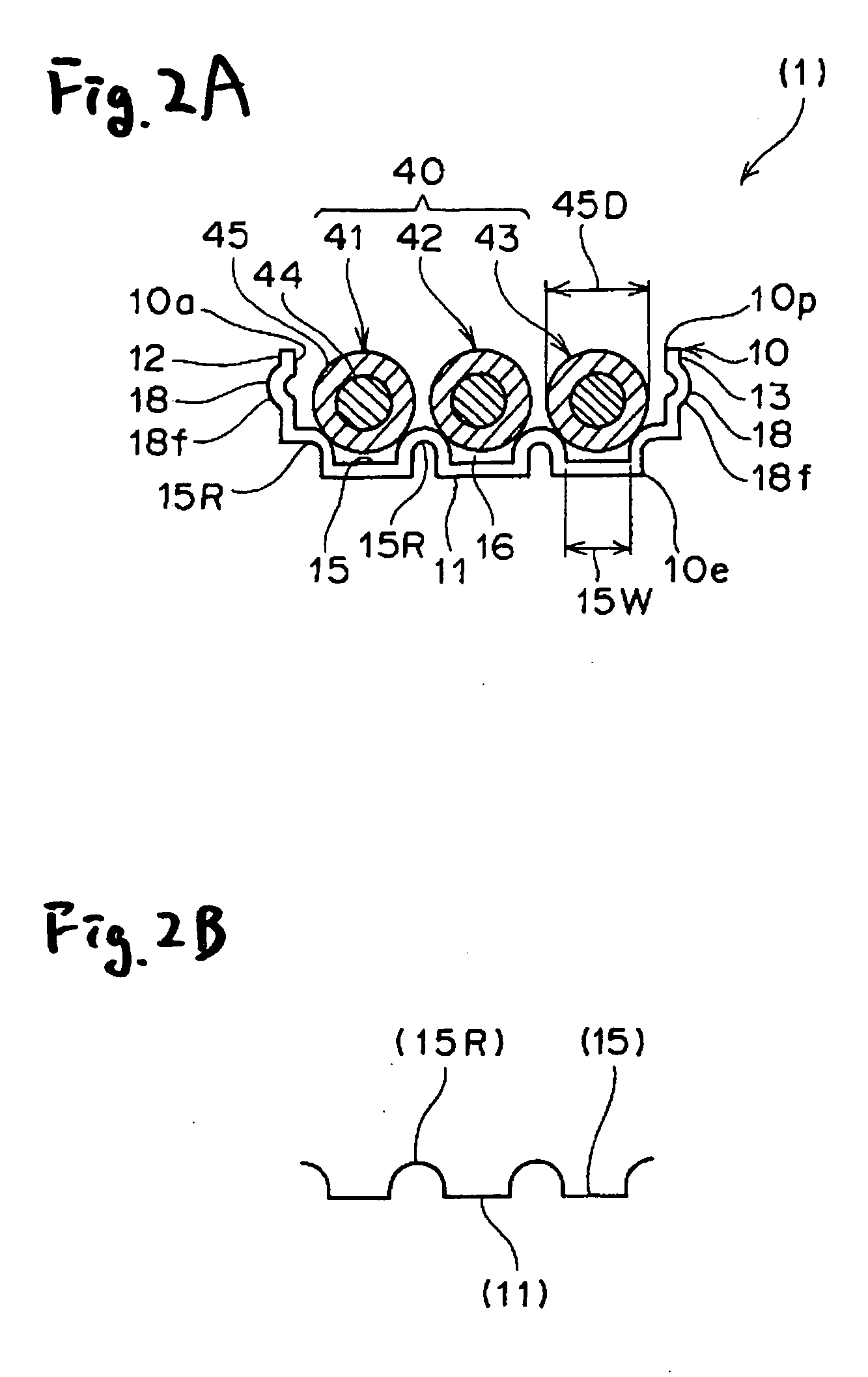
[0041]FIG. 1 is a perspective view showing the first embodiment of the protector of the invention, FIGS. 2A and 2B show the protector of the first embodiment, and FIG. 2A is a front-elevational view showing a protector body, and FIG. 2B is a conceptual view showing a bottom of the protector body.
[0042] The definition of “upper and lower directions” is the same as given in the Section of “Background Art”, and therefore detailed explanation thereof will be omitted here.
[0043] A plurality of high-voltage wires 41, 42 and 43 are received in the protector 1 shown in FIGS. 1 and 2A, and then this protector is mounted under a floor of a vehicle (not shown) such for example as a hybrid car and an electric car. The term “hybrid car” means an automobile which is capable of running, utilizing a plurality of power sources. One example of such hybrid cars is an automobile having a combination of a gasoline engine and an electric motor. One example of electric cars is a...
second embodiment
[0069] [Second Embodiment]
[0070]FIGS. 3A and 3B show a second embodiment of a protector of the invention, and FIG. 3A is a front-elevational view showing a protector body, and FIG. 3B is a conceptual view showing a bottom of the protector body.
[0071] The protector body 10 of FIGS. 1 and 2A and the protector body 20 of FIG. 3A have generally the same configuration except that their bottom walls 11 and 21 are different in shape from each other. With respect to those portions of the second embodiment identical to those of the first embodiment, only important portions thereof will be described, and detailed description thereof will be omitted.
[0072] A plurality of high-voltage wires 41, 42 and 43 are received in the protector 2 shown in FIG. 3A, and then this protector is mounted under a floor of a vehicle (not shown) such for example as a hybrid car and an electric car. There is used the protector body 20 forming the protector 2, and the wires 41, 42 and 43 are bundled together by th...
PUM
 Abstract
Description
Claims
Application Information
 - R&D
- Intellectual Property
- Life Sciences
- Materials
- Tech Scout
- Unparalleled Data Quality
- Higher Quality Content
- 60% Fewer Hallucinations
Browse by: Latest US Patents, China's latest patents, Technical Efficacy Thesaurus, Application Domain, Technology Topic, Popular Technical Reports.
© 2025 PatSnap. All rights reserved.Legal|Privacy policy|Modern Slavery Act Transparency Statement|Sitemap|About US| Contact US: help@patsnap.com