Apparatus for inflating and deflating

a technology of inflating and deflating apparatus, applied in the field of apparatus, can solve the problems of high cost and complicated process of conventional apparatus, and achieve the effects of simple and fast process, low cost, and simple and fast installation

Inactive Publication Date: 2005-02-24
WU NA
View PDF3 Cites 8 Cited by
  • Summary
  • Abstract
  • Description
  • Claims
  • Application Information

AI Technical Summary

Benefits of technology

[0008] The primary advantage of the invention is that the apparatus for inflating and deflating can be produced in a simple and fast process at a low cost. It is simpler and faster to make the cylinder 10 and the block 40 separately and assembled them than to make a cylinder with a thick closed end. It is simpler and faster to install the check valve 47 on the block 40 than to put a spring-biased ball in a passage in a thick closed end of a cylinder.

Problems solved by technology

The complicated process renders a low throughput and a high cost of this conventional apparatus.

Method used


Image

  • Apparatus for inflating and deflating
  • Apparatus for inflating and deflating
  • Apparatus for inflating and deflating

Examples


first embodiment

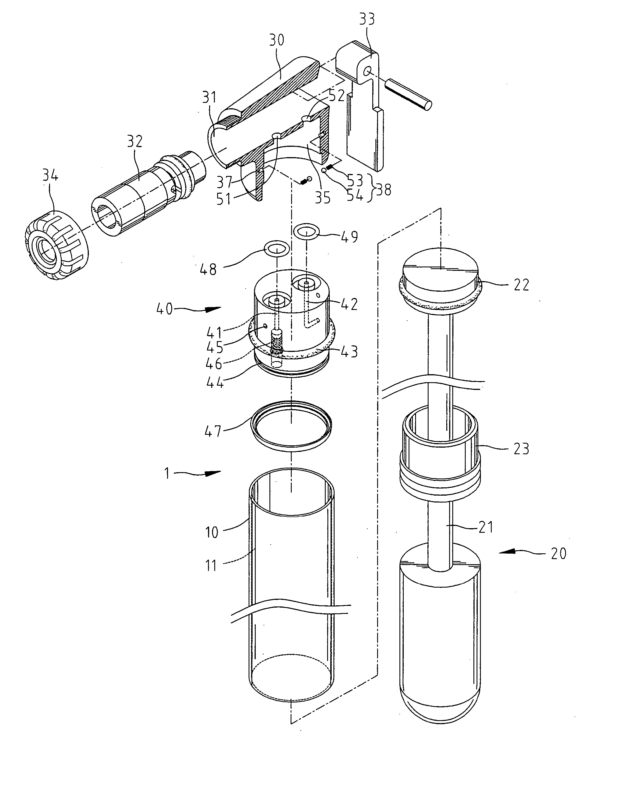
[0028] Referring to FIGS. 1 through 3, there is shown an apparatus 1 for inflating and deflating according to the present invention. The apparatus 1 includes a cylinder 10, a piston 22 put in the cylinder 10, a valve 40 provided on the cylinder 10 and a nozzle 30 provided on the valve 40.

[0029] The cylinder 10 defines a space 11 with a first open end and a second open end.

[0030] A piston rod 21 includes a first end connected with the piston 22 and a second end connected with a handle 20 for reciprocating the piston 22 in the cylinder 10. At the first open end of the cylinder 10, a seal 23 is provided between the cylinder 10 and the piston rod 21.

[0031] The block 40 is fit in the second open end of the cylinder 10. The block 40 defines a first passage 41 and a second passage 42. The first passage 41 extends from a first end of the block 40 to an opposite second end of the same. The second passage 42 extends from the first end of the block 40 to the periphery of the same. That is, t...

second embodiment

[0042]FIGS. 12 through 16 show an apparatus for inflating and deflating according to the present invention. The second embodiment is identical to the first embodiment except that the check valve 47 is arranged in an opposite direction. Accordingly, the second embodiment is operated in a different manner.

[0043] The apparatus 1 is ready for deflating. The first portion of the upper space 31 is communicated with the second passage 42 through the first aperture 51. The second portion of the upper space 31 is communicated with the first passage 41 through the second aperture 52. Although not shown, a valve of an inflatable object is inserted in the first portion of the upper space 31.

[0044] Referring to FIG. 13, the piston 22 is moved from the block 40. Air is drawn into the cylinder 10 from the inflatable object through the second passage 42. As best shown in FIG. 14, air cannot travel into the cylinder 10 from the exterior through the first passage 41 because of the check valve 46.

[0...


PUM


Abstract

An apparatus for inflating and deflating an inflatable object includes a cylinder with two open ends. A block is installed in one of the open ends of the cylinder. The block defines a first passage and a second passage. A first check valve is installed in the first passage. A second check valve is installed in the second passage. A piston is reciprocated in the cylinder. A nozzle defines a first aperture for communication with the inflatable object and a second aperture for communication with the exterior. The nozzle is rotationally mounted on the cylinder between a deflating position and an inflating position. In the deflating position, the first aperture is communicated with the first passage, and the second aperture the second passage. In the inflating position, the first aperture is communicated with the second passage, and the second aperture the first passage.

Description

CROSS-REFERENCE [0001] The present invention is a continuation-in-part application of U.S. patent application Ser. No. 10 / 396,232.BACKGROUND OF INVENTION [0002] 1. Field of Invention [0003] The present invention relates to an apparatus and, more particularly, to an apparatus for inflating and deflating. [0004] 2. Related Prior Art [0005] Referring to FIG. 17, a conventional apparatus for inflating and deflating an inflatable object is shown. This conventional apparatus includes a cylinder 100 with a closed end and an open end. The closed end of the cylinder 100 is sufficiently thick in order to define a first passage 110 and a second passage 120. A first check valve 111 is provided in the first passage 110 in order to allow air to travel into the cylinder 100 only. A second check valve 121 is provided in the second passage 120 in order to allow air to travel from the cylinder 100 only. A nozzle 300 is attached to the closed end of the cylinder 100. The nozzle 300 defines a first spa...

Claims


Application Information

Patent Timeline
IPC IPC(8): F04B33/00
CPCF04B33/005F04B33/00
Inventor WU, SCOTT
Owner WU NA
Why Eureka
Try Eureka