System, method, and apparatus for aerodynamic diverter integrated with a diffuser in a bypass channel for applications in a disk storage device

a technology of bypass channel and aerodynamic diverter, which is applied in the direction of recording information storage, maintaining head carrier alignment, instruments, etc., can solve the problems of objectionable drag and disk base drag, and achieve the effect of streamlining air flow, reducing flow-induced and reducing the vibration of the disk and actuator arm

Inactive Publication Date: 2005-02-24
WESTERN DIGITAL TECH INC
View PDF26 Cites 19 Cited by
  • Summary
  • Abstract
  • Description
  • Claims
  • Application Information

AI Technical Summary

Benefits of technology

[0011] One embodiment of a system, method, and apparatus for streamlining air flow inside of a hard disk drive is disclosed. The air flow is guided into a bypass channel. Each disk is provided with a stationary afterbody. The afterbody is shaped such that an expanding duct is created for the flow coming off each disk. An expanding aerodynamic duct or diffuser provides a gradually expanding passage so that the speed of the air flow can gradually, rather than abruptly, decrease and the pressure can rise. A set of flow diverter fins are integrally formed with the diffuser and extend between the disks to extract more air mass out of the disk stack. The fins reduce flow-induced vibration of the disks and actuator arm. This design reduces losses in system momentum due to sudden expansion of the air or gas in the drive.
[0012] The present invention also ensures a smooth recovery process of pressure from kinetic energy in the entering flow field, which reduces the amount of power required by the spindle motor. The downstream diffuser and flow diverter fins receive air flow spun off the disks while reducing the rate of cross sectional expansion, and consequential turbulence, of the air as it travels from among the disk surfaces around the actuator and non-aerodynamic disk drive components. Upon return of the bypass flow to the disk pack, air flow reentering the disk pack is accelerated in a channel of diminishing cross section to allow efficient energy conversion from pressure energy to kinetic energy prior to merging of the bypass air flow with the air flow among the disks.
[0013] The present invention utilizes a comb-like structure with fins that protrude into the spinning disk pack. In one embodiment, the structure fulfills an aerodynamic function only. However, the structure may also be configured to perform a filtration function, in which case the structure may be formed from a filtration substance. The efficacy of the filtration material may be enhanced, for example, by incorporation of electric charges (electret). The structure may be provided with linear or rounded tapers. However, smooth, edge-free tapers are desirable. For example, since the contraction is required to re-accelerate the air flow into the disk pack, the leading edges of the contraction are preferably rounded.

Problems solved by technology

As a result, present designs cause objectionable disk base drag due to the disk wakes in the bypass channel.
Moreover, there is also objectionable drag due to re-acceleration of the slow, bypass air flow around the actuator.

Method used


Image

  • System, method, and apparatus for aerodynamic diverter integrated with a diffuser in a bypass channel for applications in a disk storage device
  • System, method, and apparatus for aerodynamic diverter integrated with a diffuser in a bypass channel for applications in a disk storage device
  • System, method, and apparatus for aerodynamic diverter integrated with a diffuser in a bypass channel for applications in a disk storage device

Examples


Embodiment Construction

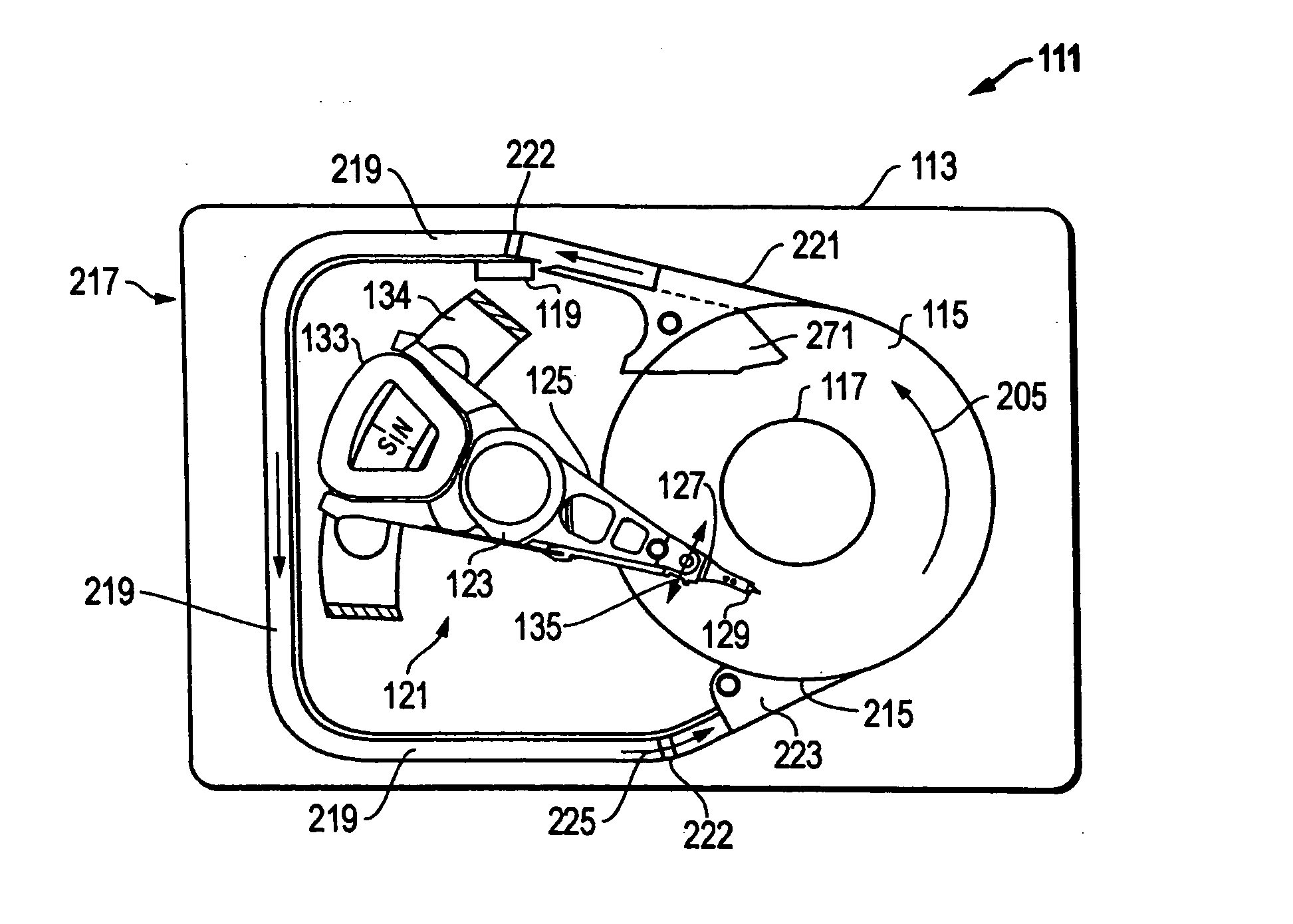
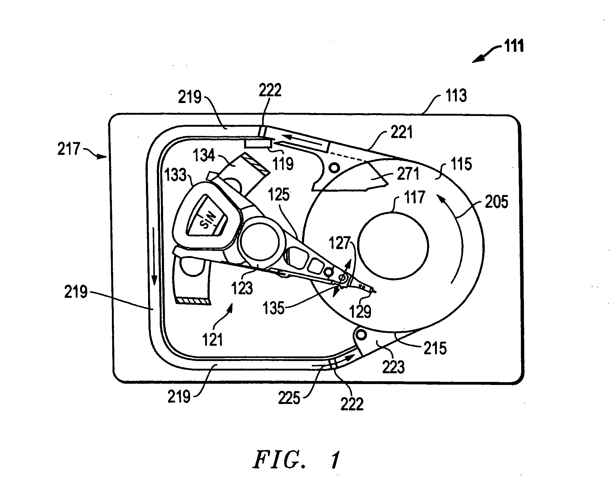
[0022] Referring to FIG. 1, a schematic drawing of one embodiment of an information storage system comprising a magnetic hard disk file or drive 111 for a computer system is shown. Drive 111 has an outer housing or base 113 containing a disk pack having at least one media or magnetic disk 115. The disk or disks 115 are rotated (see arrows 205) by a spindle motor assembly having a central drive hub 117. An actuator 121 comprises a plurality of parallel actuator arms 125 (one shown) in the form of a comb that is movably or pivotally mounted to base 113 about a pivot assembly 123. A controller 119 is also mounted to base 113 for selectively moving the comb of arms 125 relative to disk 115.

[0023] In the embodiment shown, each arm 125 has extending from it at least one cantilevered load beam and suspension 127. A magnetic read / write transducer or head is mounted on a slider 129 and secured to a flexure that is flexibly mounted to each suspension 127. The read / write heads magnetically re...


PUM


Abstract

A device streamlines air flow inside a hard disk drive with a stationary afterbody that is located adjacent to each of the disks. A diverter portion of the device enhances the volumetric flow of air through the diffuser. The overall function of the device effectively expands the air flow so that the speed of the air flow gradually decreases while pressure increases. This design reduces losses in system momentum due to sudden expansion of the air in the drive. In addition, air flow moving toward the disk pack may be contracted to allow efficient energy conversion from pressure energy to kinetic energy prior to merging of the bypass air flow with the air flow among the disks.

Description

[0001] This application is a continuation-in-part of U.S. patent application Ser. No. 10 / 644,172, filed on Aug. 20, 2003, entitled, Hard Disk Drive with Aerodynamic Diffuser, Contraction, and Fairing for Disk Base and Re-acceleration Drag Reduction, having Attorney Docket No. HSJ920030066US1, and is incorporated herein by reference.BACKGROUND OF THE INVENTION [0002] 1. Technical Field [0003] The present invention relates in general to an improved disk storage device and, in particular, to an improved system, method, and apparatus for integrating an aerodynamic diverter with a bypass channel in a disk storage device. [0004] 2. Description of the Related Art [0005] Data access and storage systems typically comprise one or more storage devices that store data on magnetic or optical storage media. For example, a magnetic storage device is known as a direct access storage device (DASD) or a hard disk drive (HDD) and includes one or more disks and a disk controller to manage local operati...

Claims


Application Information

Patent Timeline
IPC IPC(8): G11B5/60G11B33/14G11B25/04
CPCG11B5/6005G11B33/1486G11B33/148G11B33/142G11B5/012
Inventor CHAN, ANDRE SIRILUTPORNHENDRIKS, FERDINANDHATCHETT, MICHAEL ROBERTSHEN, JR-YI
Owner WESTERN DIGITAL TECH INC
Why Eureka
Try Eureka