
Method and device for controlling the heating of glow plugs in a diesel engine

a technology of glow plugs and diesel engines, which is applied in the direction of electric control, lighting and heating apparatus, machines/engines, etc., can solve the problems that the calibration of glow plugs is also inconceivabl

Inactive Publication Date: 2005-02-24
BERU AG DE
View PDF7 Cites 19 Cited by
  • Summary
  • Abstract
  • Description
  • Claims
  • Application Information

AI Technical Summary

Benefits of technology

[0007] A primary object of the present invention is to provide a process and a device of the type initially described, with which the heating of the glow plugs of a diesel engine, including the thermal behavior of the glow plugs, can be controlled without using a measuring signal for feeding back the temperature of the glow plugs.
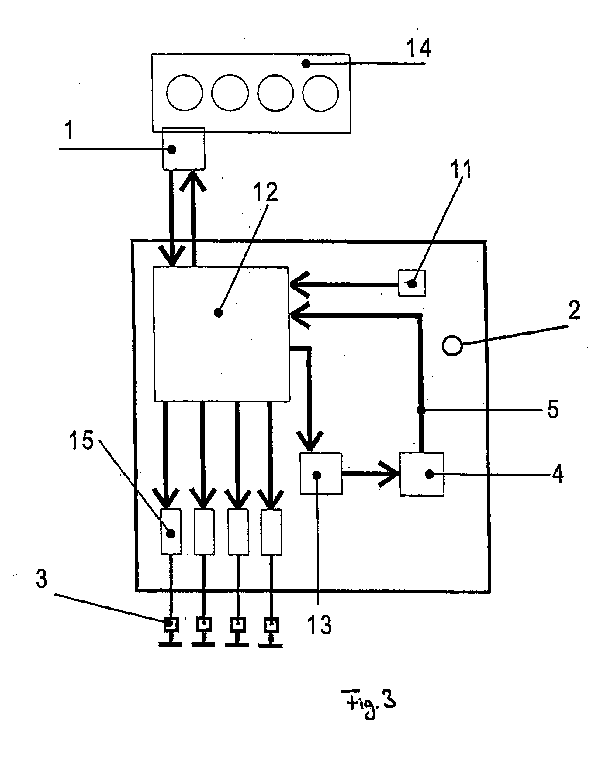
[0016] The device and process according to the present invention furnish improved repeat start protection for fast-start glow plugs and low-voltage glow plugs and offer the possibility of use as a pre-emptive regulator. This means that improved and more precise detection of the actual glow plug temperature, and guiding the glow plug temperature are possible via the more precisely and more easily detectable temperature of the physical model. The imaging and thus storing of the temperature state of the glow plugs is possible independently of the voltage supply of the electronics, so that, after full resetting, the current state of the glow plugs can be detected simply and precisely and optimal control can be selected. The physical model, which is implemented in the electronic control, can be further balanced within the context of manufacturing the electronics. According to the present invention, the memory provided is not static, but dynamic. In this way, the simulation of the cooling behavior is also possible without operating voltage, so that optimal control of the heating procedure of the glow plugs to achieve the shortest possible readiness, i.e., start capability of the engine can be achieved.

Problems solved by technology

Calibrating the glow plugs is also not conceivable, as mass-produced components are involved here.

Method used


Image

  • Method and device for controlling the heating of glow plugs in a diesel engine
  • Method and device for controlling the heating of glow plugs in a diesel engine
  • Method and device for controlling the heating of glow plugs in a diesel engine

Examples


Embodiment Construction

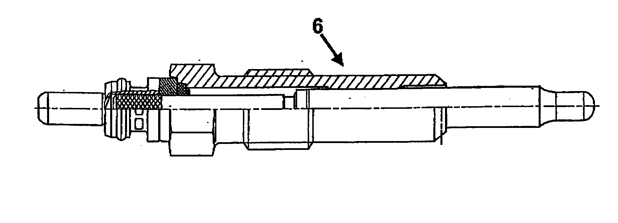
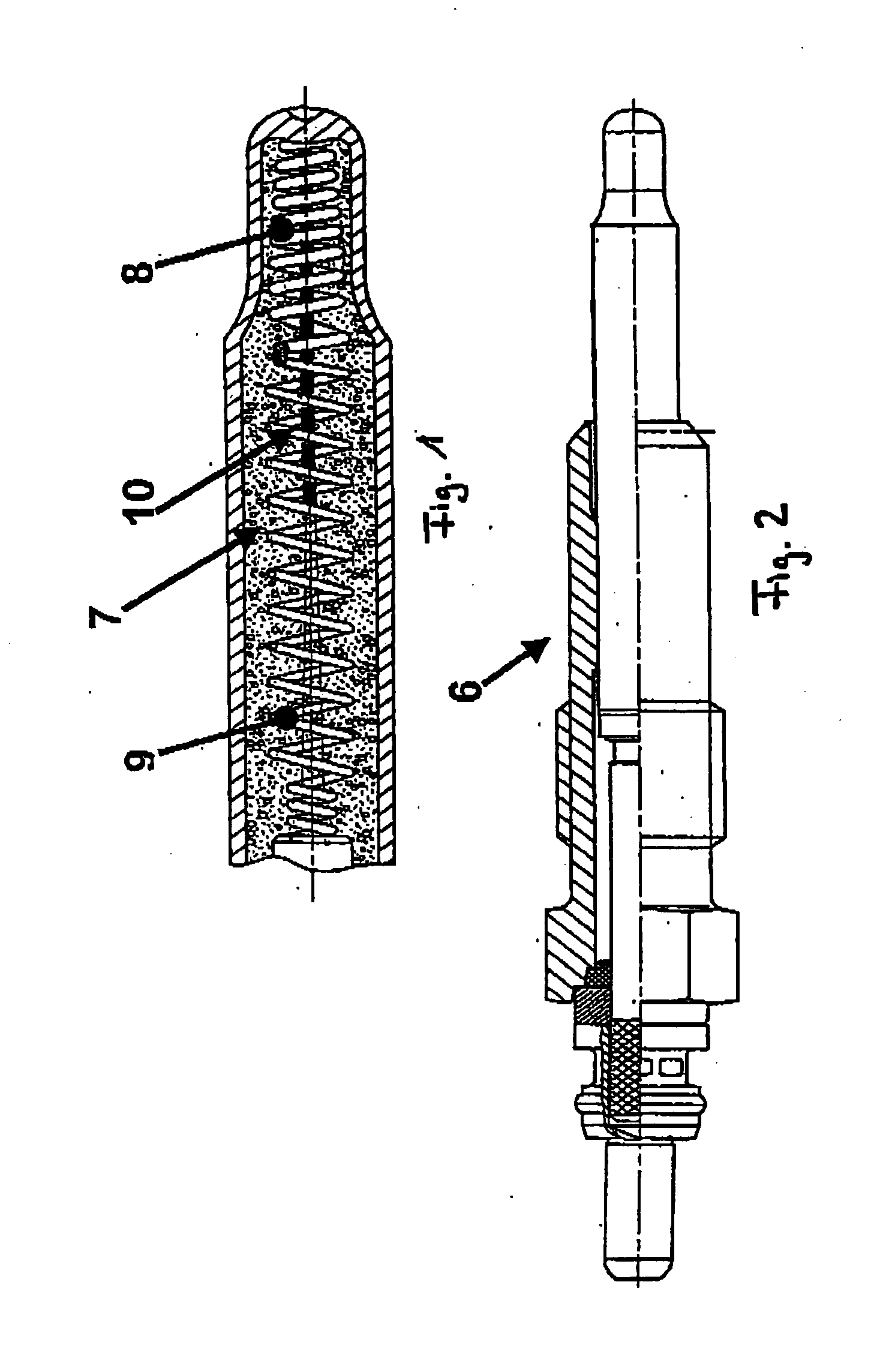
[0021] In FIGS. 1 & 2, a standard glow plug made of metal is illustrated, which has variable resistance, which generally rises with increasing temperature. Within the metal glow plug 6, for example, as illustrated in FIG. 2, there is an internal helical combination 7 of a heating element without significant temperature coefficients, namely the heating helix 8, and a heating element with positive temperature coefficients, namely the control or measuring helix 9. Since there is no sufficiently quick thermal coupling, the dynamics at the combustion chamber side core tip can be determined from the change in the resistance, and the abovementioned dynamic follows only relatively passively. In addition, the resistances of all the glow plugs vary widely from mass manufacturing and the resistance course correlates only inadequately with the temperature course. Comparing or sorting all glow plugs is inconceivable due to additional costs. Additional temperature sensors 10 certainly can be prov...


PUM


Abstract

A process and device for controlling the heating of the glow plugs of a diesel engine. To be able to take into consideration the thermal behavior of the glow plugs while controlling the current supply of the glow plugs (3) of a diesel engine, the thermal behavior of the glow plugs (3) is emulated via a physical model. Formed on the corresponding output signal of the model (4), which is proportional to the glow plug temperature, is a reference signal, which as a control value, lies on the electronic control (12) controlling the heating flow of the glow plugs (3), which accordingly controls the heating of the glow plugs (3) using the actual glow plug temperature determined from emulation.

Description

BACKGROUND OF THE INVENTION [0001] 1. Field of the Invention [0002] The invention relates to a method and a device for controlling the heating of glow plugs in a diesel engine as are used to bring the glow plugs to a predetermined set point temperature at which the engine can be started. [0003] 2. Description of Related Art [0004] The publication MTZ 10 / 2000 “Das elektronisch gesteuerte Glühsystem ISS für Dieselmotoren” [The electronically controlled ISS glow system for diesel engines] discloses a method for controlling the heating of glow plugs in a diesel engine. The glow command or glow requirement is issued after engine control initialization has been completed and after the temperature of the engine elements has been determined by way of the engine control system and subsequent successful establishment of communication between the engine control system and the glow control device. [0005] For controlling the heating of the glow plugs of a diesel engine, it is important to know t...

Claims


Application Information

Patent Timeline
Patent Type & Authority Applications(United States)
IPC IPC(8): F02D45/00F02P19/02
CPCF02P19/025
Inventor TOEDTER, OLAFSCHMITZ, HEINZ-GEORG
Owner BERU AG DE
Learn More