
Precession modulated continuously variable transmission

Inactive Publication Date: 2005-02-24
KERIAN THOMAS S
View PDF6 Cites 4 Cited by
  • Summary
  • Abstract
  • Description
  • Claims
  • Application Information

AI Technical Summary

Benefits of technology

[0010] The advantage of the precession modulated transmission of the invention is that it provides a compact speed reducing structure that is easily incorporated into a power system. The precession modulated transmission of the invention provides an efficient, low cost and low maintenance structure that provides a broad range of reduction ratios.
[0011] A further benefit of the precession modulated transmission of the invention is its ease of manufacture, assembly and reliability. The transmission of the invention further provides improved torque transmission characteristics, is tolerant to shock and overload conditions and is scalable for a variety of uses.
[0012] The precession modulated transmission is an invention offering significant advantages in power transmission by virtue of a compact design that is easily integrated into power trains. Further benefits include significant improvements in efficiency by the elimination of the pump-motor relationship of prior art axial piston and of bent axis HST's. This distinct departure from the prior art also imparts benefits concerning torque transmission. Further, the damper control system of the transmission may be used as an auxiliary power source.

Problems solved by technology

To date, many proposals for a variety of continuously variable transmissions (CVT) have been published or patented, however, few have demonstrated commercial viability despite the compelling performance potential offered by such a device.
The efficacy of these systems, however, has produced mixed results due to the many trade-offs resulting from one or more serious limitations.
HST's fill a wide range of applications and power levels, however their efficiency tends to be comparatively poor.
This inefficiency manifests itself in the large heat exchangers that are typically necessary to dispose of waste energy created by their operation.
HST's also produce undesirable high noise and vibration levels inherent to their dependency on the high volume flow of a pressurized hydraulic medium.
They also tend to be quite expensive and therefore are reserved primarily for high end, industrial or capital equipment applications.
However, because of their comparatively poor efficiency, objectionable noise and the substantial space required by supporting systems for cooling, conditioning and filtration of the hydraulic fluid, it has had little impact on other markets.
Also, due to the fact that fluid pressure and volume are at or near maximum at operating speed, significant noise and vibration typically results.
They also consume excessive amounts of fuel and generate considerable amounts of heat.

Method used


Image

  • Precession modulated continuously variable transmission
  • Precession modulated continuously variable transmission
  • Precession modulated continuously variable transmission

Examples


Embodiment Construction

[0028] The present invention relates to a precession modulated continually regulated transmission (PMT). Embodiments of the PMT, the precession modulation control assemblies and the methods of operation are shown in the drawings and discussed as follows.

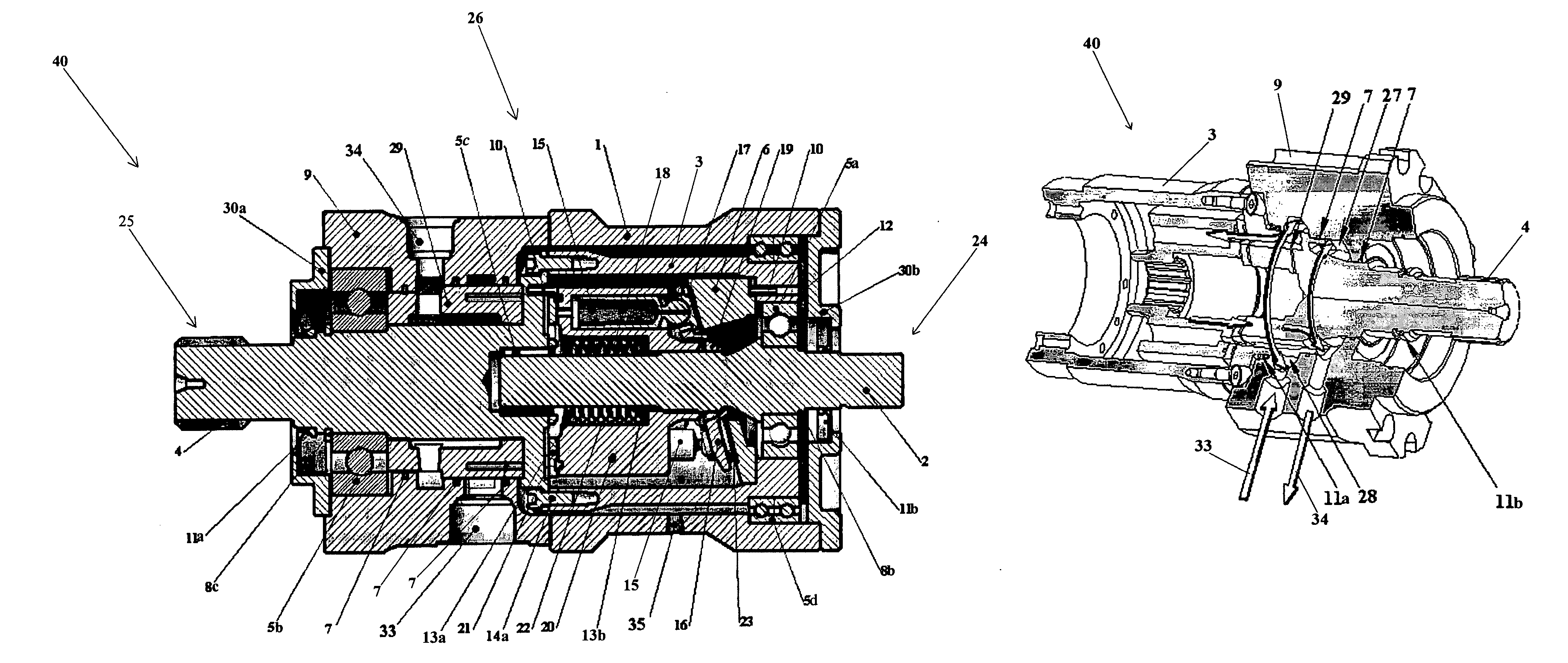
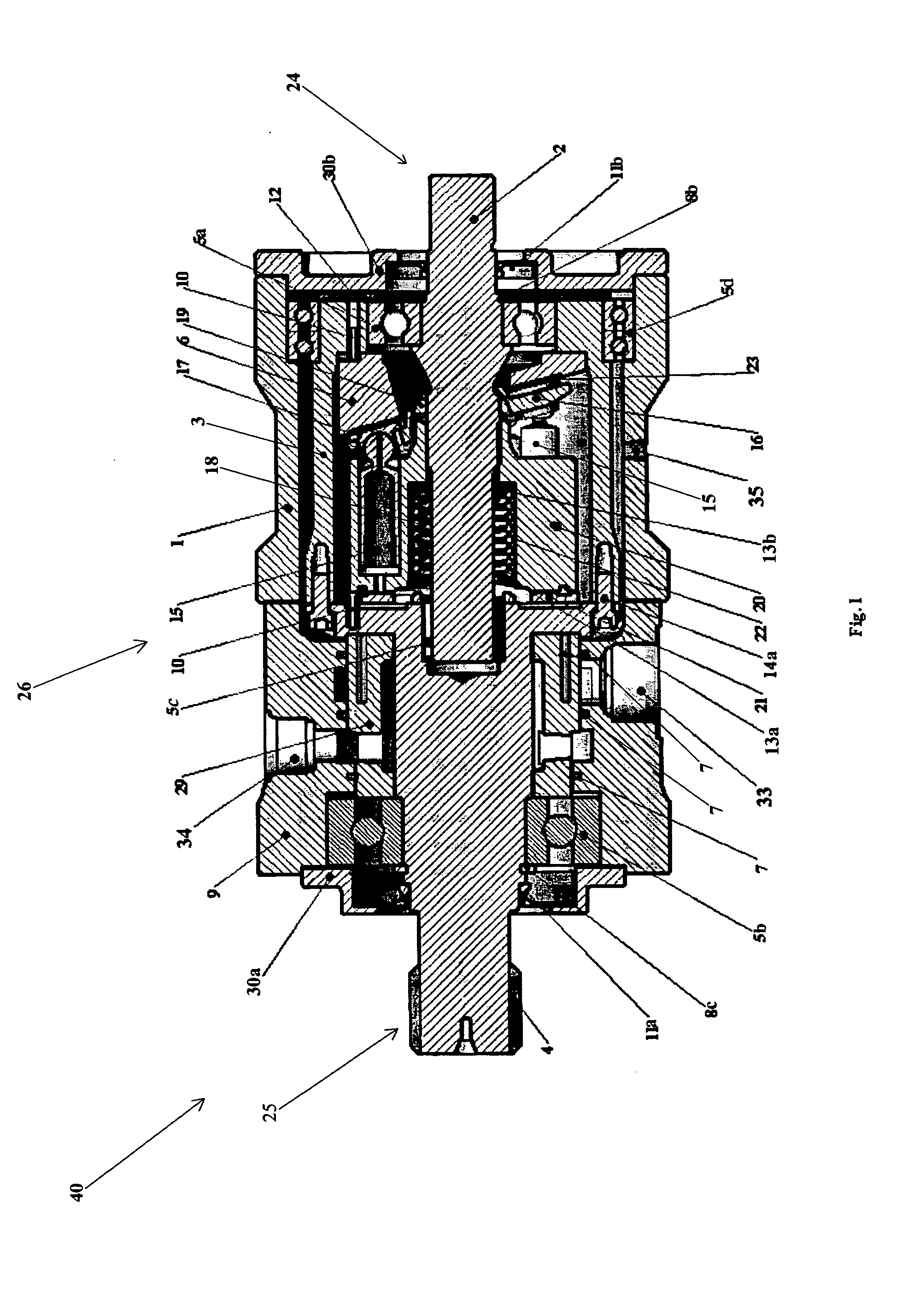
[0029] As shown in FIG. 1, an embodiment of the PMT has three principal component groups coaxially arrayed. At the center of the transmission 40 is a core group 24 enclosed by a transfer case group 25. Surrounding the core group 24 and the transfer case group 25 is the housing group 26. The core group 24, transfer case group 25 and housing group 26 are comprised of various parts set forth in FIG. 9, and are further discussed below with respect to FIGS. 10, 11 and 12, respectively, and are shown cooperating together in FIG. 1.

[0030] The preferred embodiments of the core group 24 use a hydraulic medium for damping with a system of damper pistons 15 axially arrayed within a cylinder block or carrier plate 20 to which power is imparted...


PUM


Abstract

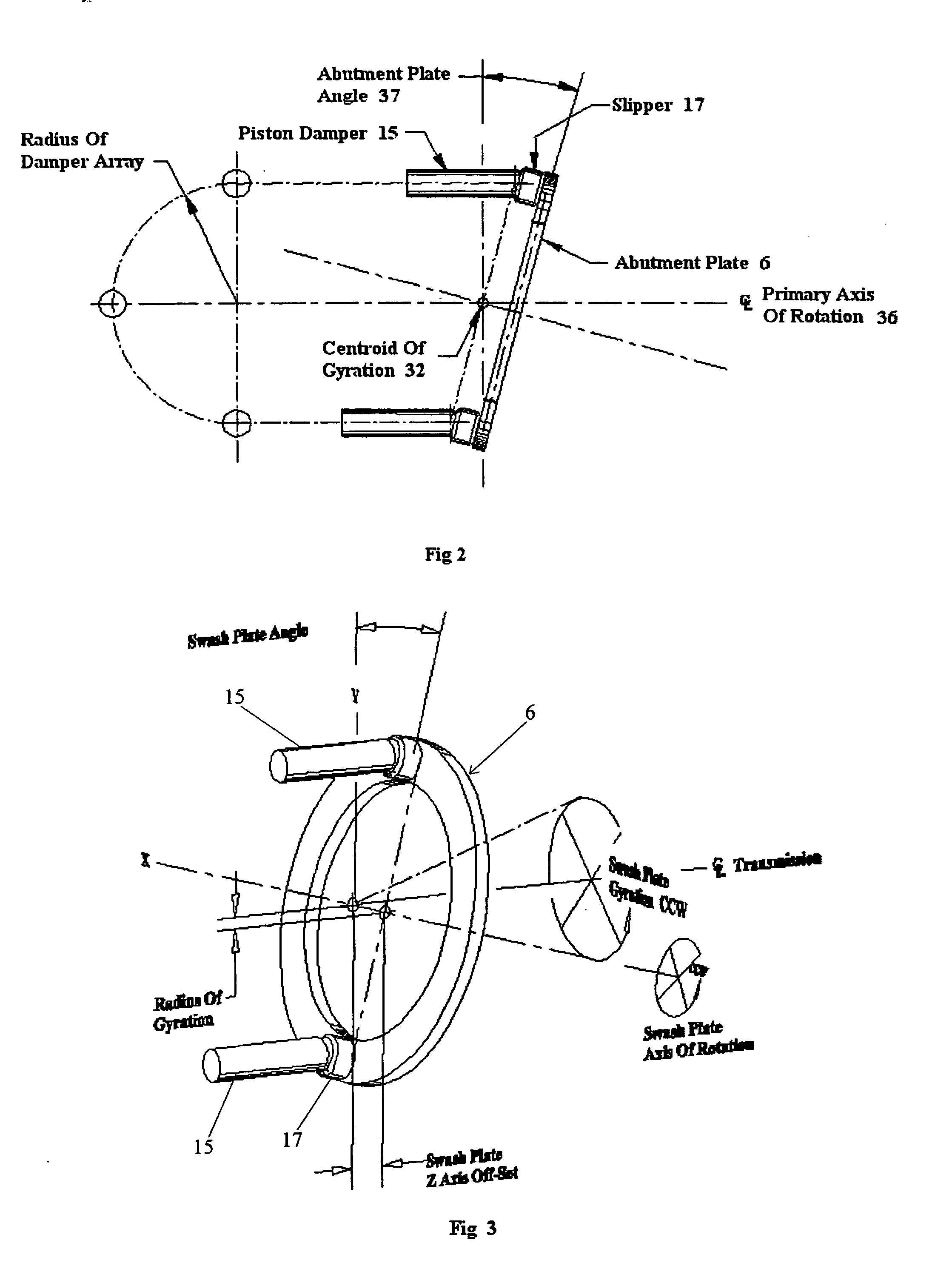
A precession modulated variable differential transmission having a transfer assembly interposed between a rotational input and output. The continuously variable differential transmission utilizes dampers to induce and control the gyrational and rotational motion of a precessing plate. A core group of elements of the transfer assembly include an axial array of dampers peripherally arranged to engage a swash plate in a torsionally rigid manner. Torque is transmitted via the swash plate to an abutment plate within the transfer case. This differential arrangement produced by interposing the damper array between the input and output results in a swash plate that exhibits the motion of a gyroscope. Its rotational speed is dictated by the prime mover while the gyration component, rotating in the same direction, is modulated by the dampers. As the gyration component alone, is translated to the transfer case, and hence the output, the relationship between the rotating moment and the gyrating moment determines the reduction ratio, and is regulated by controlling the damping rate of the damper array.

Description

[0001] This application is a continuation-in-part of Applicant's co-pending U.S. application Ser. No. 10 / 109,766, filed on or about Mar. 30, 2002, which claims the benefit of Provisional Patent Application Ser. No. 60 / 287,698, filed on or about Apr. 1, 2001.BACKGROUND OF THE INVENTION [0002] This invention relates to a continuously variable transmission assembly that utilizes an innovative process for controlling the reduction ratio, termed by the inventor, “precession modulation”. The precession modulated transmission (PMT) is able to produce a wide range of reduction ratios in a highly controllable, increment-less fashion. Variations in the reduction ratio are produced by converting the rotary motion of the input into the rotating and oscillating motion characteristic of a precessing body. As only the oscillating component is transferred to the output shaft, controlling the frequency of this component, which can be readily varied independent of input speed, varies the reduction ra...

Claims


Application Information

Patent Timeline
IPC IPC(8): F01B3/00F16H39/40
CPCF01B3/00Y10T74/18296Y10T74/18336F16H48/18
Inventor KERIAN, THOMAS S.
Owner KERIAN THOMAS S
Learn More