
Catheter drive

a catheter and drive technology, applied in the direction of catheters, dilators, surgery, etc., can solve the problems of clogging of blood vessels, less able to negotiate sharp curves, and difficult to convey pushing force along the catheter from the outside of the body to the tip, so as to reduce the resistance of fluid to travel inside the tube, increase working fluid pressure, and increase the effect of bending

Inactive Publication Date: 2005-02-10
F D CARDIO
View PDF30 Cites 54 Cited by
  • Summary
  • Abstract
  • Description
  • Claims
  • Application Information

AI Technical Summary

Benefits of technology

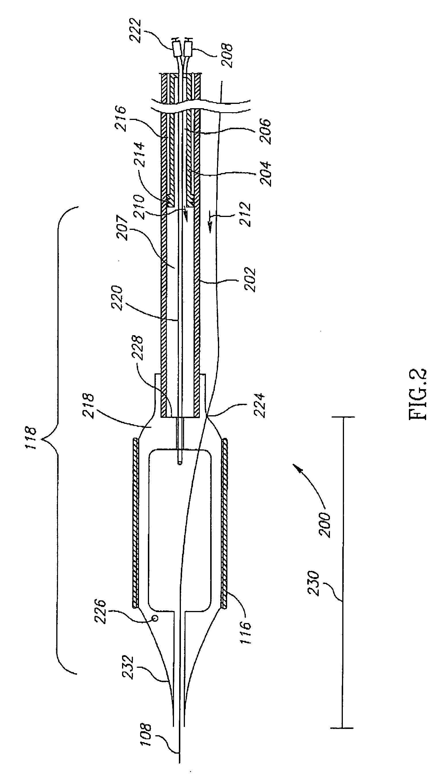
[0010] An aspect of some embodiments of the invention relates to a catheter tube which is hydraulically advanced and which has a varying diameter, such that a distal section has a narrower diameter than a proximal section. Optionally, the use of a varying diameter allows a more proximal section of the catheter tube to be stiffer. Optionally, the use of a varying diameter allows fluid resistance to travel inside the tube to be reduced. Optionally, the use of a varying diameter allows a narrower profile catheter to be provided, capable of greater bending and / or able to pass narrowings. Optionally, the stiffness of the tube itself is relatively uniform along its length.
[0011] An aspect of some embodiments of the invention relates to a fluid seal in a hydraulic catheter, in which increased working fluid pressure tends to enhance the seal. Optionally, the seal is between a moving tube and a hub. Optionally, the moving tube is a balloon inflation tube. Optionally, the moving tube is a catheter tube. Optionally, the seal is directional so that it affords less resistance to relative movement in one direction.
[0016] In an exemplary embodiment of the invention, the force is applied using fluid pressure which is optionally applied from outside the body. Optionally, a sliding fluid seal is provided between the outer and inner tubes. The fluid may be provided, for example, in the inner tube, or between the inner tube and the outer tube. Optionally, the same fluid source and path is used for advancing and for balloon inflation. Optionally, a valve is provided to release pressure and prevent over pressuring of the fluid.
[0021] Optionally, the catheter includes a stop that prevents over-extension of the catheter tip. Alternatively or additionally, the catheter includes a lock, outside the body, which (optionally selectively) prevents relative motion of the two tubes, or places a limit on such motion, for example, a limit on amount of motion and / or a limit on speed of motion.
[0053] In an exemplary embodiment of the invention, said stop, when engaged, prevents liquid flow therethrough.
[0127] In an exemplary embodiment of the invention, the system comprises a fluid inflation channel inside said inner tube. Optionally, said fluid inflation channel extends through and out of said outer tube. Optionally, the system comprises a port in said outer tube adapted to prevent fluid leakage between said outer tube and said inflation channel. Optionally, said port includes a valve whose seal improves when working fluid pressure is increased in said outer tube.

Problems solved by technology

Emboli can also cause clogging of blood vessels.
If the catheter is soft, helping it negotiating curves, it may be difficult to convey the pushing force along the catheter from outside the body to the tip.
If the catheter is stiffer, it may be less able to negotiate sharp curves.
In either case, excessive pushing forces may damage the blood vessels.
This solution is apparently not suitable for catheters used in blood vessels, especially in narrow diameter blood vessels, such as cardiac arteries and brain arteries, for example due to size considerations and geometry of surfaces tat would contact blood.

Method used


Image

  • Catheter drive
  • Catheter drive
  • Catheter drive

Examples


Embodiment Construction

[0167] Overview

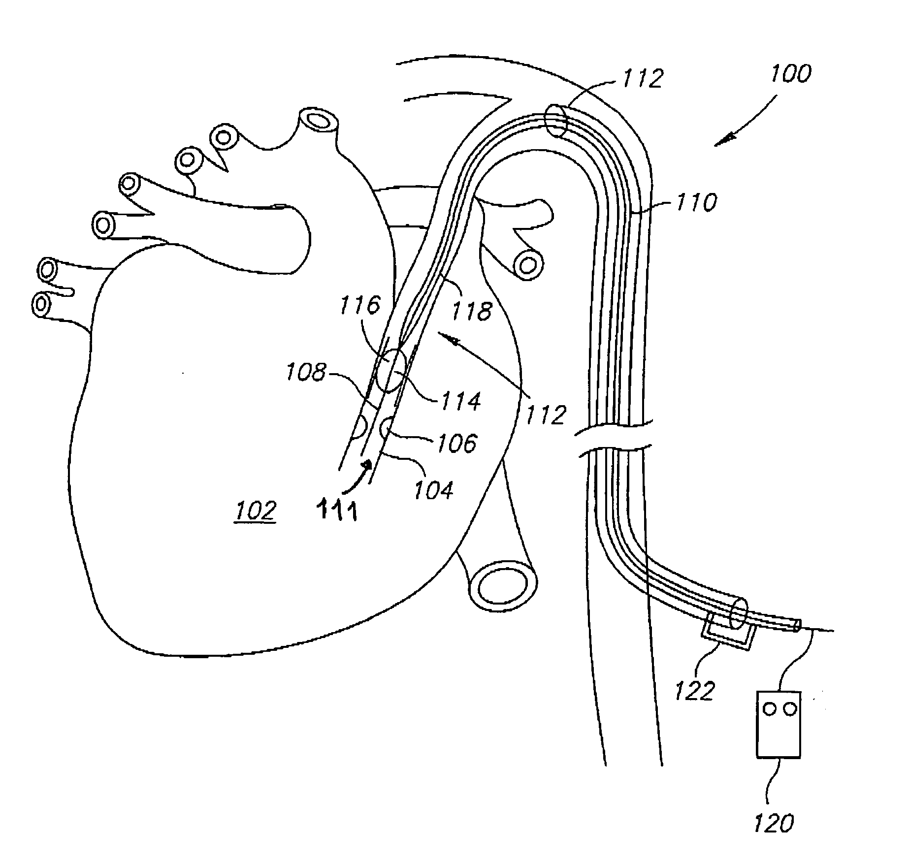
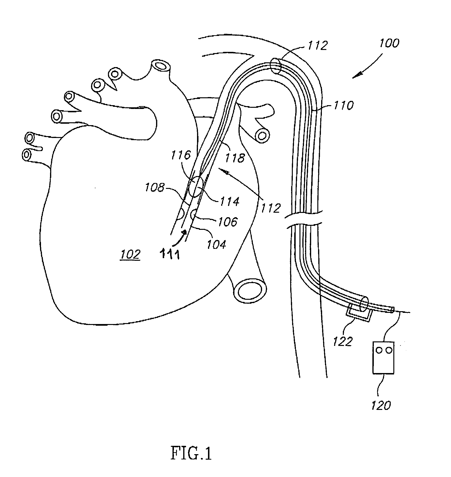
[0168]FIG. 1 is a schematic illustration of an exemplary catheter system 100 in use, in accordance with an exemplary embodiment of the invention. A heart 102 includes a coronary vessel 104 with a narrowing 106 (e.g., caused by arteriosclerosis plaque, an old stent, etc. or another types of diseased tissue, such as an emboli). Catheter system 100 includes a guide wire 108 on which rides a catheter 110, at least partly in a guiding catheter / sheath 112. Catheter 110 has a distal tip 111, which optionally includes a balloon 114 and / or a stent 116. In an exemplary embodiment of the invention, a distal section 118 of catheter 110 is advancible from sheath 112, using a force applied at or about distal section 118, as described below. A control system 120 is optional used for controlling this advance. A lock 122 is optionally provided to lock catheter 110 to sheath 112 and / or lock movement of distal section 118 to sheath 112 and / or the rest of catheter 110.

[0169] It should ...


PUM


Abstract

A catheter drive system, comprising: an inner tube adapted for inserting into a human body; an outer tube configured to slidably and snugly engage said inner tube, outside of a human body; and a pushing mechanism adapted to apply a pushing force to said inner tube less than 100 mm from an end thereof, such that said inner tube can extend at least 200 mm.

Description

RELATED APPLICATIONS [0001] This application is a continuation-in-part of PCT Application No. PCT / IL03 / 00995, filed on Nov. 25, 2003 and is a continuation-in-part of U.S. application Ser. No. 10 / 303,064, filed on Nov. 25, 2002. This application is also related to a PCT Application filed on even date, titled “Stent Positioning Using Inflation Tube”, attorney docket number 378 / 04071. The disclosure of all of these applications are incorporated herein by reference.FIELD OF THE INVENTION [0002] The present invention relates to devices and methods for catheter navigation. BACKGROUND OF THE INVENTION [0003] Blood vessels can suffer from various diseases, in particular arteriosclerosis, in which obstructions form in a lumen of a blood vessel, narrowing or clogging it. Emboli can also cause clogging of blood vessels. A common treatment method for narrowing is inserting a catheter with a balloon at its end to a clogged portion of the blood vessel, inflating the balloon and possibly leaving a...

Claims


Application Information

Patent Timeline
IPC IPC(8): A61M25/01A61M25/08
CPCA61M25/0122
Inventor CHERMONI, ISRAEL
Owner F D CARDIO
Learn More