
Method for manufacturing a golf club face

Inactive Publication Date: 2005-02-10
TAYLOR MADE GOLF
View PDF35 Cites 53 Cited by
  • Summary
  • Abstract
  • Description
  • Claims
  • Application Information

AI Technical Summary

Benefits of technology

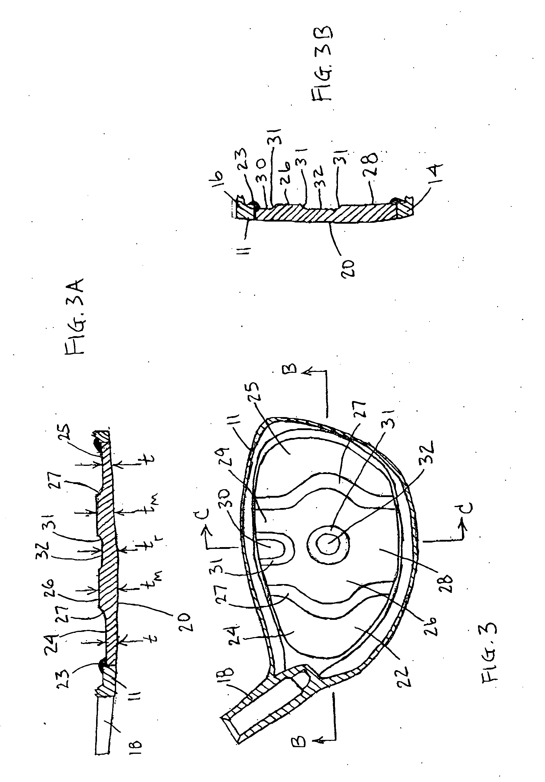
[0012] The invention provides a method of manufacturing a golf club face plate having substantial thickness variation for enhanced performance. The method includes the steps of providing a rolled sheet of metal material having an initial thickness and forming a blank having a prescribed outer shape from the material. The method also includes machining a second side of the blank such that the resulting face plate has a variable thickness. The variable thickness includes a first thickness less than or equal to the initial thickness, a second thickness less than the first thickness and a third thickness less than the second thickness. The machining is performed over a substantial portion of the surface area of the second side.
[0013] An advantage of the rolled sheet material is that it can have a very fine, directional grain microstructure that results in improved strength and ductility compared to other materials and manufacturing methods Either a CNC lathe or milling machine may be used; however, for an axisymmetric face thickness a CNC lathe is preferred and for an asymmetric face thickness a CNC end mill is preferred. The club head may be a wood-type or iron, and titanium or steel alloys may be used.

Problems solved by technology

There are limitations on how large a golf club head can be manufactured, which is a function of several parameters, including the material, the weight of the club head and the strength of the club head.
Because of the use of lightweight materials such as titanium for the face plate, a problem arises in the stresses that are transmitted to the face-crown and face-sole junctions of the club head upon impact with the golf ball.
However, these club heads fail to ultimately provide much forgiveness to off center hits for all but the most expert golfers.

Method used


Image

  • Method for manufacturing a golf club face
  • Method for manufacturing a golf club face
  • Method for manufacturing a golf club face

Examples


Embodiment Construction

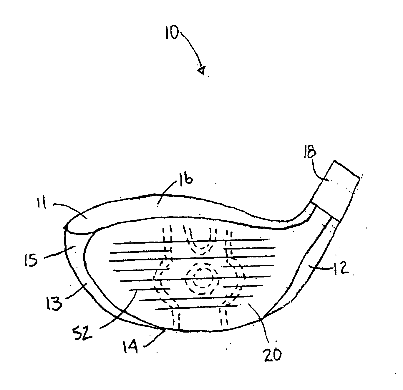
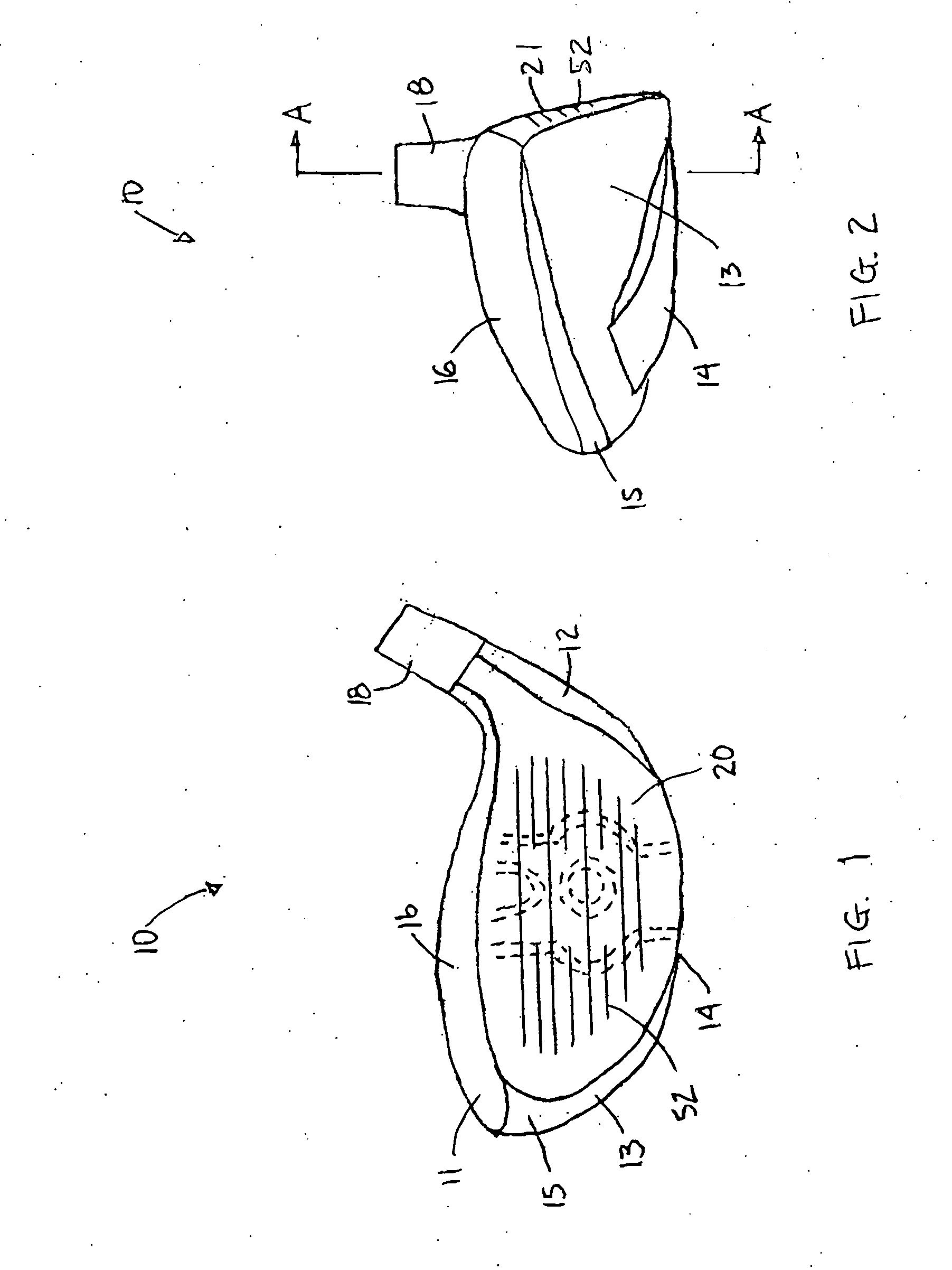
[0032] The drawings depict preferred embodiments of face plates achieved by methods of the present invention, the golf club face plates being for different types of golf club heads. With reference to FIG. 1, a club head 10 is shown that is similar to many metal wood club heads that are known in the art. Club heads within the scope of the invention are not necessarily limited to the shapes depicted. The club head 10 comprises a hollow metallic body 11 and a face plate 20. The body comprises a heel portion 12, a toe portion 13, a sole portion 14, skirt or side portion 15 and a crown portion 16 that cooperate to define a periphery 17 for an opening (see FIG. 3) for the face plate. The club head is normally connected to a shaft (not shown) by a hosel 18 that is integrally formed with the body.

[0033] Preferably, the body and / or face plate is constructed of steel, titanium or alloys thereof, but alternatively the body may comprise a composite or metal matrix material. The face plate may ...


PUM

PropertyMeasurementUnit
Lengthaaaaaaaaaa
Lengthaaaaaaaaaa
Fractionaaaaaaaaaa

Abstract

A method of manufacturing a face plate for a golf club head is presented to provide face having substantial thickness variation for enhanced performance. The method includes the steps of providing a rolled sheet of metal material having an initial thickness and forming a blank having a prescribed outer shape from the material. The method also includes machining a second side of the blank such that the resulting face plate has a variable thickness. The machining is such that the plate has a first thickness less than or equal to the initial thickness, a second thickness less than the first thickness and a third thickness less than the second thickness. The machining is performed over a substantial portion of the surface area of the second side. Either a CNC lathe or milling machine may be used; however, for an axisymmetric face thickness a CNC lathe is preferred and for an asymmetric face thickness a CNC end mill is preferred. The club head may be a wood-type or iron, and titanium or steel alloys may be used.

Description

CROSS-REFERENCE TO RELATED APPLICATION [0001] This application is a continuation of prior application Ser. No. 10 / 288,551, filed Nov. 4, 2002, which is herein incorporated by reference.BACKGROUND OF THE INVENTION [0002] The present invention relates generally to golf club heads and, more particularly, to golf club heads having a face plate of variable thickness. [0003] Modern golf clubs have typically been classified as either woods, irons or putters. The term “wood” is an historical term that is still commonly used, even for golf clubs that are constructed of steel, titanium, fiberglass and other more exotic materials, to name a few. The woods are now often referred to as “metal woods.” The term “iron” is also an historical term that is still commonly used, even though those clubs are not typically constructed of iron, but are rather constructed of many of the same materials used to construct “woods.”[0004] Many advancements have been achieved, particularly over the past couple of ...

Claims


Application Information

Patent Timeline
IPC IPC(8): A63B53/04
CPCA63B53/04A63B2053/0416A63B2053/0458Y10T29/49995A63B2053/0433A63B53/047A63B53/0466A63B53/0416A63B53/0433A63B53/0458A63B60/00
Inventor WILLETT, KRAIG A.KRAUS, STEPHEN A.BEACH, TODD P.HOFFMAN, JOSEPH H.
Owner TAYLOR MADE GOLF
Learn More