Laser driver, optical disk apparatus using the same, and laser control method

Inactive Publication Date: 2005-02-10
HITACHI CONSUMER ELECTRONICS CORP
View PDF16 Cites 0 Cited by
  • Summary
  • Abstract
  • Description
  • Claims
  • Application Information

AI Technical Summary

Benefits of technology

[0006] Accordingly, it is an object of the present invention to provide a laser driver which is capable of measuring the superimposed frequency of semiconductor laser simply and accurately, and provide an optical disk apparatus which uses the laser driver.
[0007] Another object of the present invention is to provide an optical disk apparatus which is capable, within the apparatus, of controlling the superimposed frequency of semiconductor laser.
[0011] The inventive laser control method, which is intended for an optical disk apparatus which drives a semiconductor laser with a high-frequency current to project a laser beam onto an optical disk thereby to reproduce data recorded on the optical disk, is designed to measure the frequency of the high-frequency current and control the frequency by using the measured frequency. Specifically, it detects the above-mentioned error rate or jitter and controls the semiconductor laser by using the detection result and measured frequency so that the error rate or jitter may be minimal.

Problems solved by technology

However, this laser driver involves a problem of the disparity among individual devices, and some laser drivers having an invariable or same frequency setting are found to vary their output frequencies out of the intended frequency range D due to the disparity in frequency of the high-frequency current 5 produced by the oscillator 4.
The frequency disparity of the high-frequency current 5, which is attributable to the semiconductor manufacturing process, is difficult to make smaller, giving rise to the need of frequency adjustment for the superimposed current before the shipment from the factory.

Method used


Image

  • Laser driver, optical disk apparatus using the same, and laser control method
  • Laser driver, optical disk apparatus using the same, and laser control method
  • Laser driver, optical disk apparatus using the same, and laser control method

Examples


first embodiment

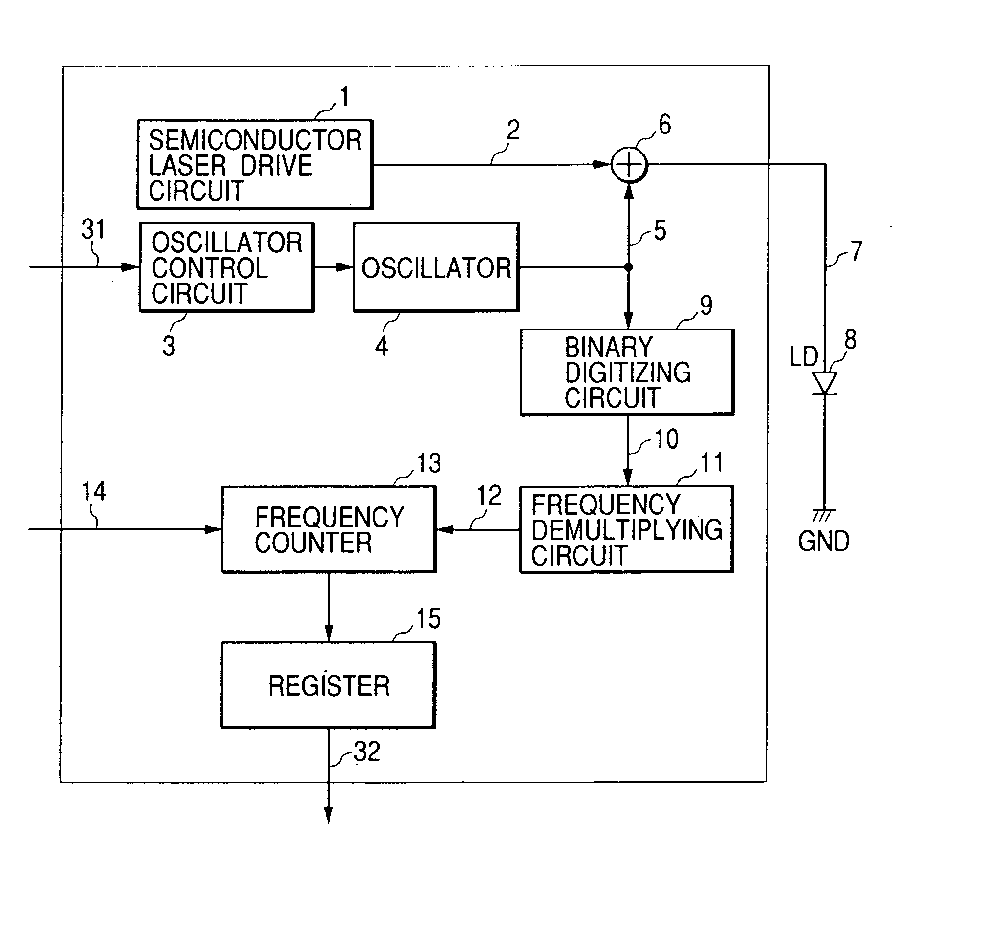
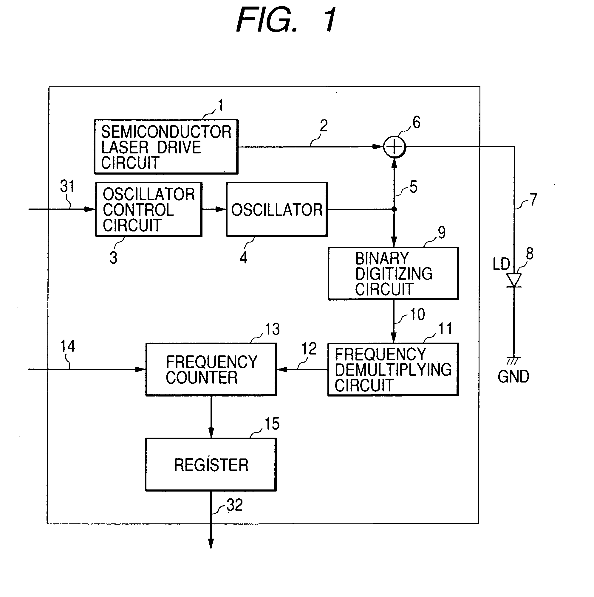
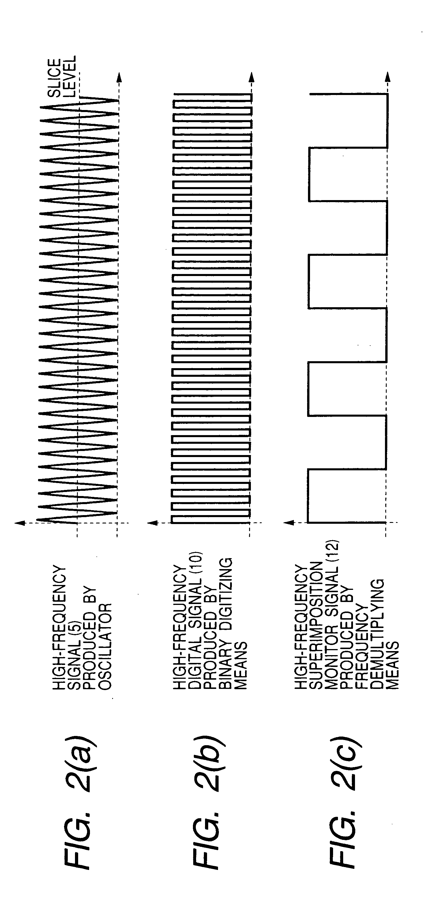
[0021]FIG. 1 shows by block diagram the circuit arrangement of the laser driver based on this invention. Functional blocks of FIG. 1 identical to those of the conventional laser driver shown in FIG. 4 are referred to by the common symbols. The laser driver of this embodiment includes a frequency measuring circuit which measures the frequency of a high-frequency current produced by an oscillator 4 in a high frequency superimposing oscillator, and in this example it is made up of a binary digitizing circuit 9, a frequency demultiplying circuit 11, and a frequency counter 13. The laser driver further includes a register 15 which holds the value of frequency of the superimposed current measured by the frequency measuring circuit.

[0022] The oscillator 4 is a variable-frequency oscillator having its output frequency controlled continuously in response to an input analog voltage. The oscillator 4 outputs a high-frequency current 5 having its frequency and amplitude controlled by an oscilla...

second embodiment

[0025] Next, the laser driver based on this invention will be explained with reference to FIG. 3. As mentioned previously, it is possible by using the laser driver of FIG. 1 to measure the frequency with in the optical disk apparatus. Whereas, in case the laser driver is designed to undergo the frequency adjustment before the shipment from the factory, the laser driver shown in FIG. 1 has its frequency counter 13 and register 15 eliminated and has additional provision of an output terminal for the superimposition monitor signal 12 on the optical disk apparatus to become as shown in FIG. 3. The superimposition monitor signal 12 is input into an external measuring instrument to adjust the frequency of the superimposed current. Although this scheme necessitates the initial adjustment in the factory, it is to measure the superimposition monitor signal, instead of measuring a weak unwanted radiation or EMI, allowing the simpler provision of an antenna and spectrum analyzer.

third embodiment

[0026] Next, this invention will be explained with reference to FIG. 5, which shows by block diagram the optical disk reproduction apparatus of this embodiment.

[0027] In FIG. 5, a laser driver 17 is derived from the counterpart shown in FIG. 1, and it is made up of an oscillator 4 which generates a high-frequency current, a frequency counter which measures the frequency of the high-frequency current from the oscillator 4 based on a reference clock signal 14, and a register 15 which holds the measured frequency value. The laser driver 17 outputs a semiconductor laser diode current 7, which energizes a laser diode 8 fitted on an optical head 18 to emit a laser beam.

[0028] The optical head 18 projects the laser beam of the laser diode 8 onto the optical disk 20 and detects the reflected light from the optical disk with a photo detector 19. The photo detector 19 functions to convert the sensed light intensity into an electrical signal, thereby outputing a servo error signal 21 and a re...


PUM


Abstract

An optical disk apparatus uses a laser driver which can measure the frequency of the high-frequency superimposed current of the semiconductor laser simply and accurately. The apparatus includes a semiconductor laser which emits a laser beam onto the optical disk, a laser driver which drives the semiconductor laser with a current, with the high-frequency current being superimposed thereon, and measures the frequency of the high-frequency current, and a main controller which controls the frequency of the high-frequency current produced by the laser driver by using the frequency measured by the laser driver.

Description

BACKGROUND OF THE INVENTION [0001] The present invention relates to an optical disk apparatus which records and reproduces information on an optical disk, and particularly to a laser driver which is useful for improving the quality of reproduced signal and to an optical disk apparatus which uses the laser driver. [0002] Optical disk information reproduction apparatus based on the semiconductor laser adopts the high frequency superimposition scheme in which a high-frequency current is superimposed on a d.c. current for driving the semiconductor laser in order to reduce the laser noise which emerges due to the interference between the semiconductor laser and the reflected light from the recording medium. However, despite the use of the high frequency superimposition scheme, there was found a phenomenon of the presence of a significant residual laser noise. A study conducted recently revealed that this phenomenon is caused by the relaxation oscillation which arises when the semiconduct...

Claims


Application Information

Patent Timeline
IPC IPC(8): G11B7/125H01S5/062H01S5/0687
CPCH01S5/0687G11B7/1263
Inventor NIHEI, MAKOTOKAKU, TOSHIMITSUASADA, AKIHIROHOSHINO, TAKASHI
Owner HITACHI CONSUMER ELECTRONICS CORP
Why Eureka
Try Eureka