Fluorescence lifetime measurement apparatus
a fluorescence lifetime and measurement apparatus technology, applied in the direction of luminescent dosimeters, optical radiation measurement, instruments, etc., can solve the problems of difficult to reduce the error the plurality of time gates setting is inappropriately large, and the calculation of the fluorescence lifetime takes a long tim
- Summary
- Abstract
- Description
- Claims
- Application Information
AI Technical Summary
Problems solved by technology
Method used
Image

Examples
first embodiment
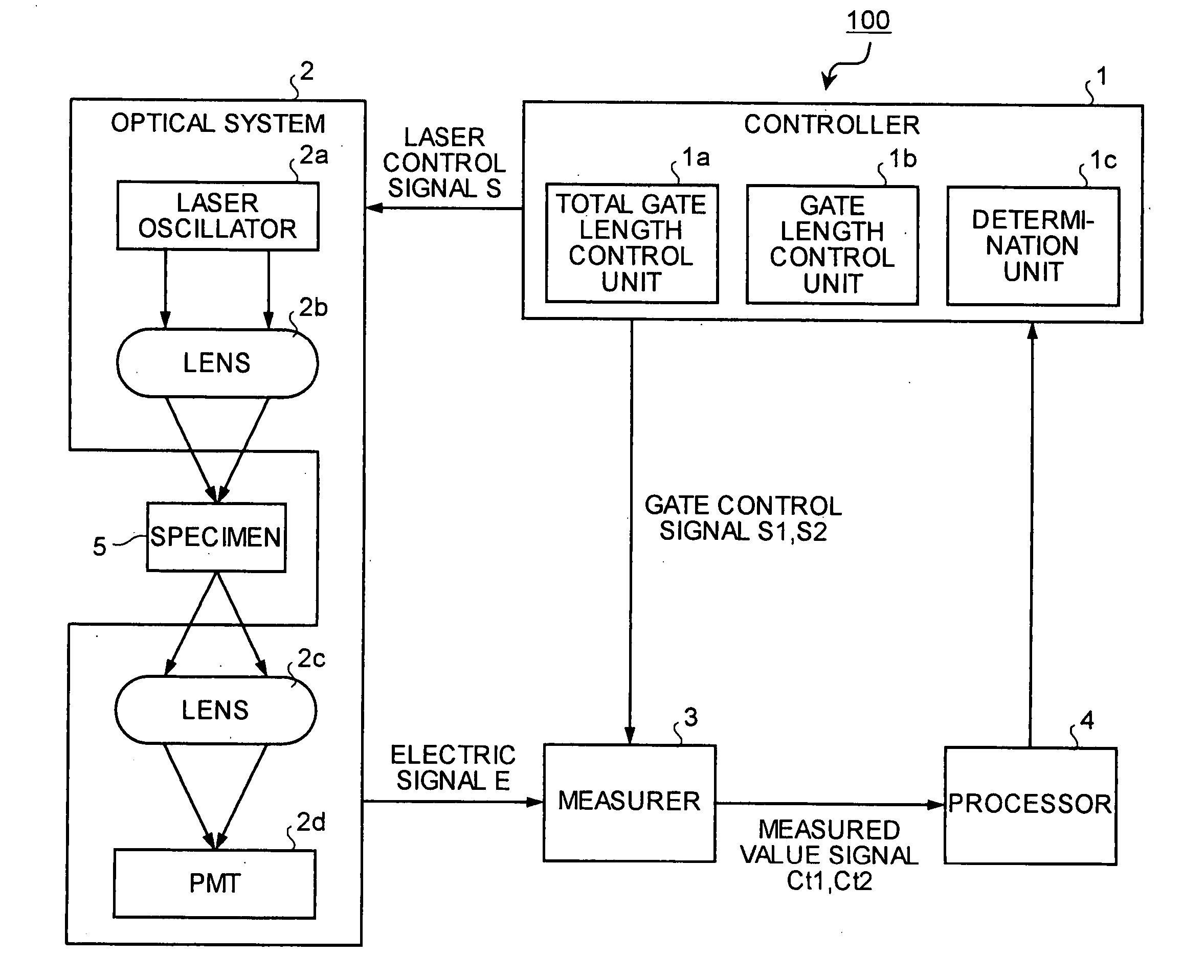
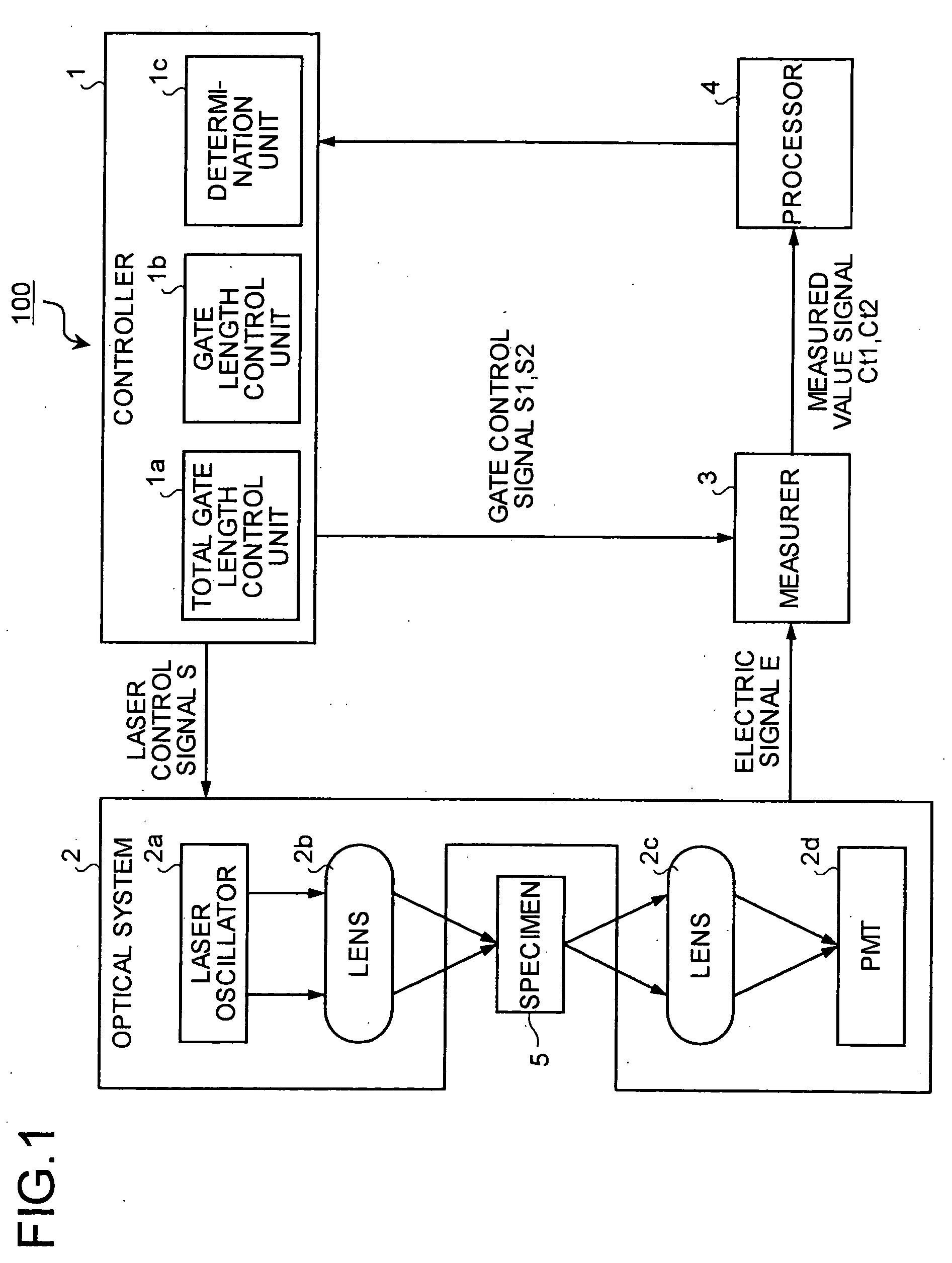
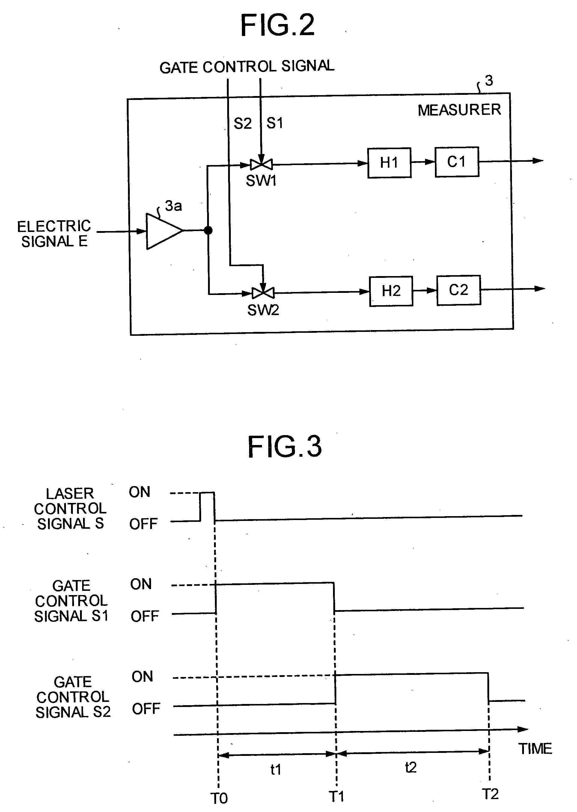
FIG. 1 is a block diagram of a fluorescence lifetime measurement apparatus 100 according to the present invention. The fluorescence lifetime measurement apparatus 100 includes a controller 1, an optical system 2, a measurer 3, and a processor 4.
The controller 1 includes a total gate length control unit 1a, a gate length control unit 1b, and a determination unit 1c. The total gate length control unit 1a controls a total gate length that is a total time window from a start to an end of measurement of the number of fluorescence photons. The gate length control unit 1b controls each gate length obtained by dividing the total gate length into a plurality of gate lengths. The determination section 1c determines whether a calculated value of a fluorescence lifetime satisfies a predetermined condition and settles the fluorescence lifetime.
The optical system 2 includes a laser oscillator 2a, lenses 2b and 2c, and a photo multiplier tube (PMT) 2d acting as a photoelectric converter. The la...
second embodiment
A second embodiment is explained below. In the first embodiment, the number of fluorescence photons is measured just after the specimen 5 is irradiated with the pulse excitation light. In the second embodiment, however, a delay time is set before measurement of the number of fluorescence photons starts so that the number can be calculated accurately.
FIG. 13 is a block diagram a fluorescence lifetime measurement apparatus 100B according to the second embodiment of the present invention. As shown in FIG. 13, a controller 1B includes a time delay control unit 1d. The time delay control unit 1d sets gate control signals S1 and S2 such that measurement of fluorescence photons is delayed until emission of fluorescence photons becomes equal to or less than a light sensitivity of the PMT 2d.
Since an emission probability of fluorescence photons emitted from an excited specimen follows Poisson distribution, the number of fluorescence photons is maximized just after emission of the excitatio...
third embodiment
A third embodiment is explained below. In the first and second embodiments, the processor 4 calculates and outputs the fluorescence lifetime τ, and the determination unit 1c determines whether the gate delay time t1 and the total gate length (t1+t2) are appropriate based on the fluorescence lifetime τ. In the third embodiment, however, a first gate length and a second gate length are set to the same time length, and a time difference between a time at which the first gate length starts and a time at which the second gate length starts is set as a gate delay time. Whether the gate delay time t1 and the total gate length (t1+t2) are appropriate depends on measured value signals Ct1 and Ct2 output from the measurer 3 so that unnecessary calculation of the fluorescence lifetime τ can be omitted.
FIG. 16 is a block diagram of a fluorescence lifetime measurement apparatus 100C according to the third embodiment. As shown in FIG. 16, the measurer 3 measures the number of fluorescence photons...
PUM
| Property | Measurement | Unit |
|---|---|---|
| fluorescence lifetime measurement | aaaaa | aaaaa |
| length | aaaaa | aaaaa |
| fluorescence | aaaaa | aaaaa |
Abstract
Description
Claims
Application Information
 - R&D
- Intellectual Property
- Life Sciences
- Materials
- Tech Scout
- Unparalleled Data Quality
- Higher Quality Content
- 60% Fewer Hallucinations
Browse by: Latest US Patents, China's latest patents, Technical Efficacy Thesaurus, Application Domain, Technology Topic, Popular Technical Reports.
© 2025 PatSnap. All rights reserved.Legal|Privacy policy|Modern Slavery Act Transparency Statement|Sitemap|About US| Contact US: help@patsnap.com