
Heater controller for gas sensor ensuring stability of temperature control

a technology of temperature control and controller, which is applied in the direction of electrical control, instruments, electrical circuits, etc., can solve the problems of reducing the measurement accuracy of gas sensors, and achieve the desired resolution, improve the convergence of the temperature of the gas sensors, and increase the feedback gain

Inactive Publication Date: 2005-02-10
DENSO CORP
View PDF4 Cites 26 Cited by
  • Summary
  • Abstract
  • Description
  • Claims
  • Application Information

AI Technical Summary

Benefits of technology

The present invention provides a heater controller for a gas sensor that ensures stability of control of temperature of the gas sensor regardless of disturbances, such as changes in ambient temperature. The heater controller works by controlling the heating of the gas sensor up to a desired activation temperature using a feedback control system. The heater power controlling circuit determines a feedback gain based on the deviation of the temperature of the gas sensor from a target value and changes the feedback gain accordingly to ensure stability of control. The heater controller can be used in various gas sensors equipped with a solid electrolyte body for heating the gas sensor.

Problems solved by technology

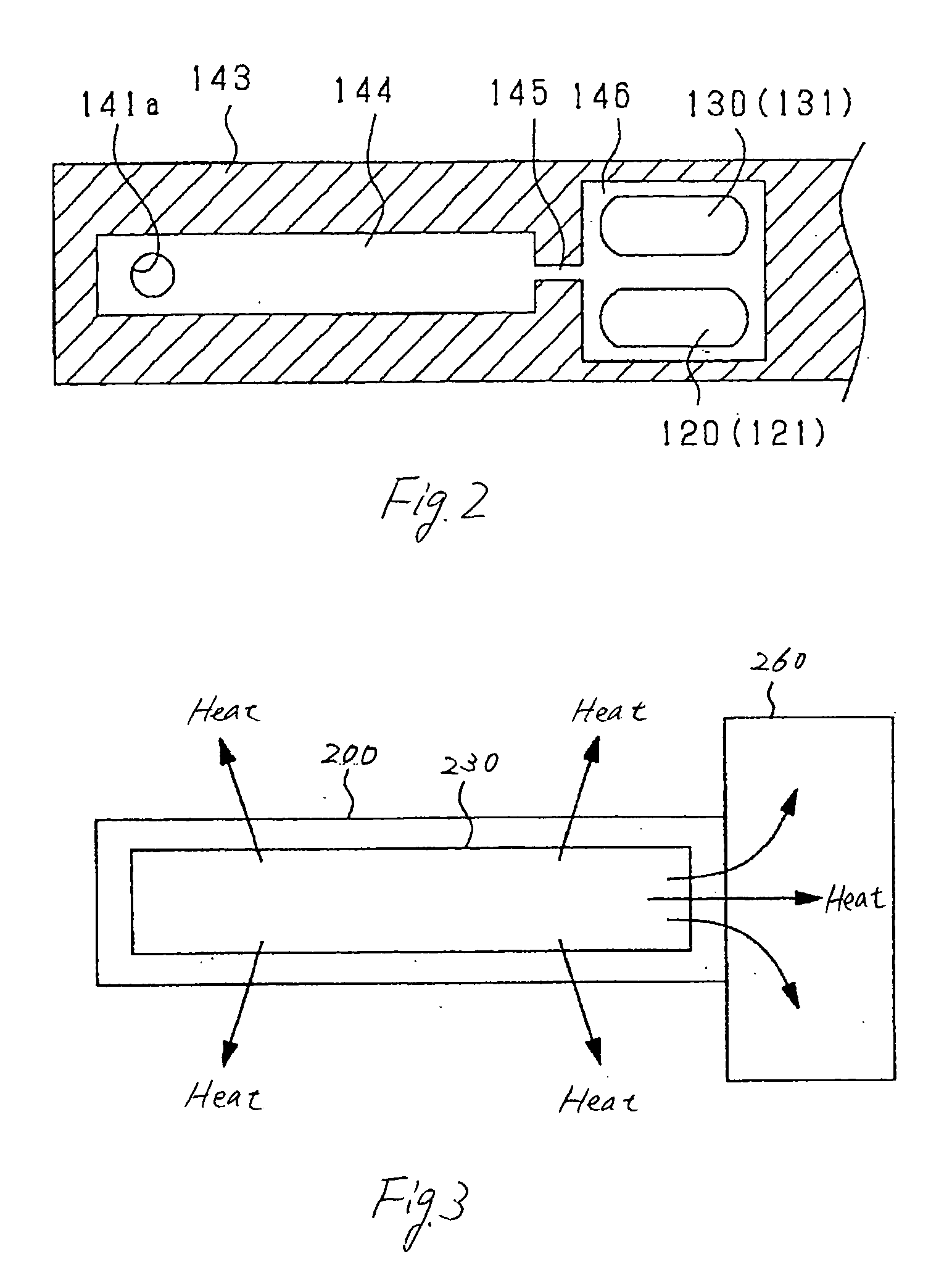
Usually, when an ambient temperature changes, it will be a disturbance to control the temperature of the body of the gas sensor, thus resulting in reduction in measurement accuracy of the gas sensor.

Method used


Image

  • Heater controller for gas sensor ensuring stability of temperature control
  • Heater controller for gas sensor ensuring stability of temperature control
  • Heater controller for gas sensor ensuring stability of temperature control

Examples


first embodiment

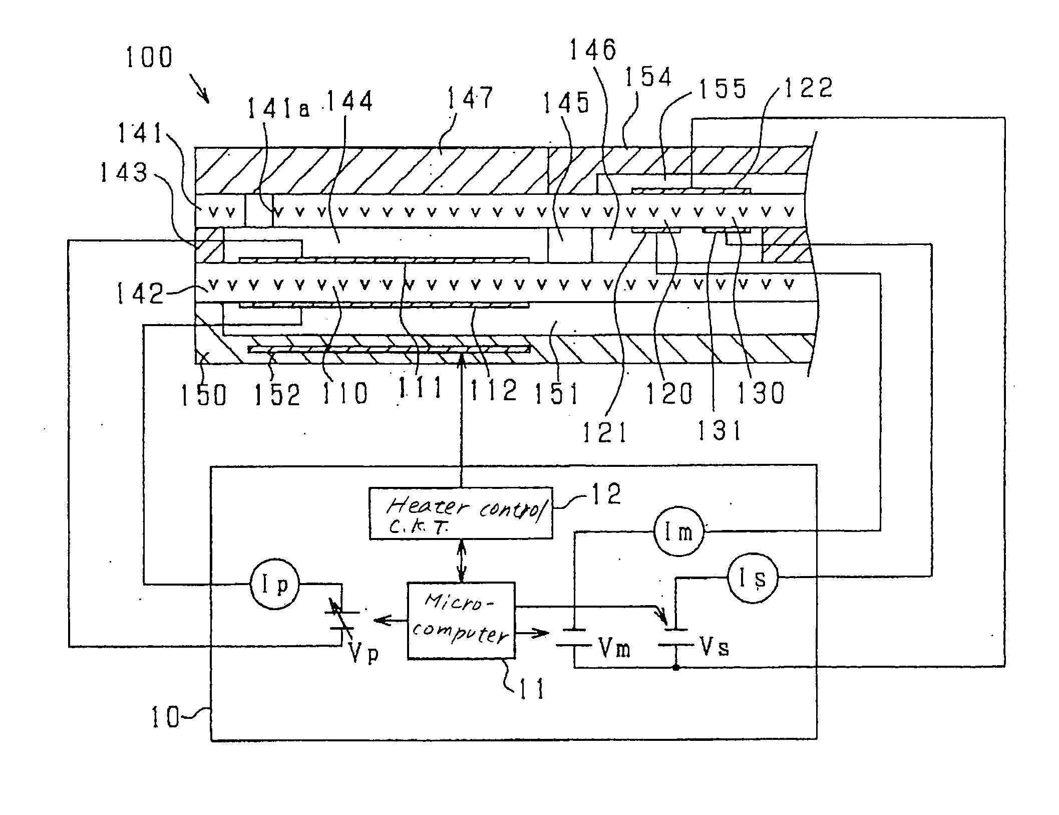
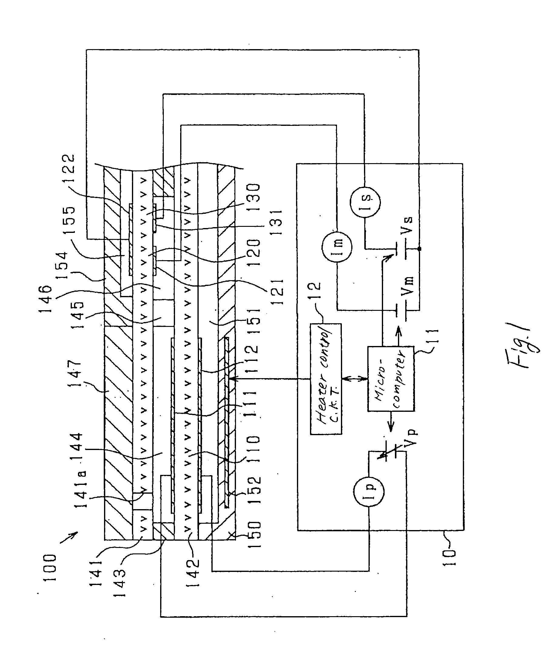
Referring now to the drawings, wherein like numbers refer to like parts in several views, particularly to FIG. 1, there is shown a gas concentration measuring device according to the invention which consists essentially of a gas sensor 100 and a sensor control circuit implemented by an electronic control unit (ECU) 10.

The gas sensor 100 is installed, for example, in an exhaust pipe of an automotive internal combustion gasoline engine and exposed to exhaust gasses emitted from the engine. The gas sensor 100 is of a limiting current type and works to produce a limiting current as a function of concentration of a specified component contained in the exhaust gasses. The sensor ECU 10 is responsive to the output from the gas sensor 100 to determine the concentration of the specified gas component. In the following discussion, the gas sensor 100 is assumed to measure at least the concentration of nitrogen oxide (NOx).

FIG. 1 illustrates an internal structure of a top portion of the gas s...

second embodiment

FIG. 10 is a flowchart of a sub-program executed in step 150 of FIG. 6 to control the operation of the heater 152 according to the invention. The program is to keep the P and I gains at an initially-selected constant value when the monitor cell admittance MAdm lies within a target range defined around the target value and to change the P and I gains to a value greater than the initially-selected constant value when the monitor cell admittance MAdm lies out of the target range or when the P and I gains are changing at a rate which is expected to cause the monitor cell admittance MAdm to change out of the target range.

After entering the program, the routine proceeds to step 301 wherein it is determined whether a condition in which the temperature of the heater 152 should be increased is met or not. If a YES answer is obtained, then the routine proceeds to step 302 wherein the duty cycle of the heater control signal to the heater control circuit 12 is set to 100% to increase the tempe...


PUM

PropertyMeasurementUnit
time Taaaaaaaaaaa
temperatureaaaaaaaaaa
concentrationaaaaaaaaaa

Abstract

A heater controller designed to control the thermal energy produced by a heater under feedback control for heating a body of a gas sensor up to a desired activated temperature. The heater controller works to determine a feedback gain such a proportional or an integral gain as a function of a deviation of the temperature of the gas sensor from a target one and change it based on a condition in which the temperature of the gas sensor is changing from the target value. This ensures the stability of control of the temperature of the gas sensor regardless of a disturbance such as a change in ambient temperature and keeps the accuracy of gas measurement at a higher level.

Description

BACKGROUND OF THE INVENTION 1. Technical Field of the Invention The present invention relates generally to a heater controller designed to control the thermal energy produced by a heater for heating a body of a gas sensor up to a desired activated temperature, and more particularly such a heater controller which ensures the stability of control of the temperature of a gas sensor regardless of a control disturbance such as a change in temperature or flow rate of a gas to be measured by the gas sensor. 2. Background Art Some of modern automotive vehicles equipped with an internal combustion engine have a gas sensor installed in an exhaust system of the engine which measures the concentration of a specified component of exhaust emissions from the engine for use in controlling the exhaust emissions. Typical gas sensors used in such a system have a solid electrolyte body made of zirconia which forms an electrochemical cell sensitive to a target gas component. Keeping the accuracy of...

Claims


Application Information

Patent Timeline
Patent Type & Authority Applications(United States)
IPC IPC(8): G01N27/41F02D41/14F02D45/00G01N27/406G01N27/416H05B1/02
CPCF02D41/1494H05B1/0236G01N27/4067
Inventor NIWA, MITSUNOBUKUROKAWA, EIICHIHADA, SATOSHI
Owner DENSO CORP
Learn More