
Patsnap Eureka
For R&D, Patsnap Eureka makes reading and utilizing patents & technical documents easy.
Patsnap Eureka AIR
Designed for self-driven R&D workflows. Generate viable solutions, solve complex R&D challenges, empower your innovation with AI.

Patsnap Eureka Materials
Designed for material experts only. Revolutionize your material R&D, from search, analyze, to developing new materials.

TechResearch
Generate reliable direction feasibility study reports for your R&D in just a few steps.

TechSeek
Discover and master advanced knowledge NOW. Basics, ideas, possibilities, all at once.

TechMind
As an expert in R&D Theories, TechMind can generates customized viable solutions instantly.

TechRisk
Analyze your overall solution with one click, know your potential R&D risks in advance.

TechMonitor
Get weekly tech updates, stay abreast of the latest tech innovations and key insights.
Production process for vinyl chloride polymer
a production process and vinyl chloride technology, applied in the direction of water installations, lavatory sanitory, disinfection, etc., can solve the problems of increasing fish eyes, unavoidable foaming phenomenon at the surface of liquid phase, and increasing the possibility of scale generation on the internal walls of the polymerization vessel at the gas-liquid interfa
- Summary
- Abstract
- Description
- Claims
- Application Information
AI Technical Summary
Benefits of technology
Problems solved by technology
Method used
Image


Examples
example 1
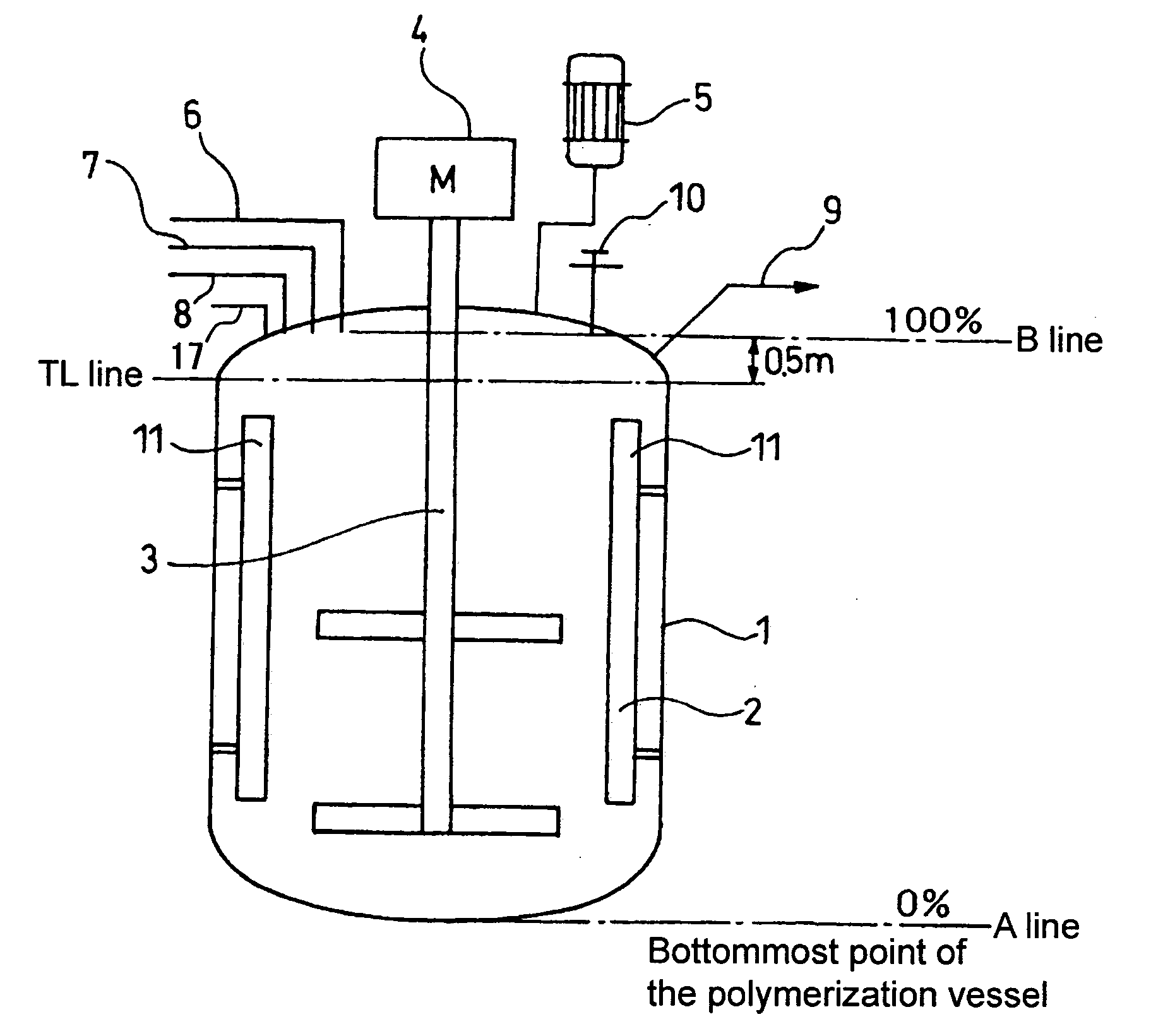
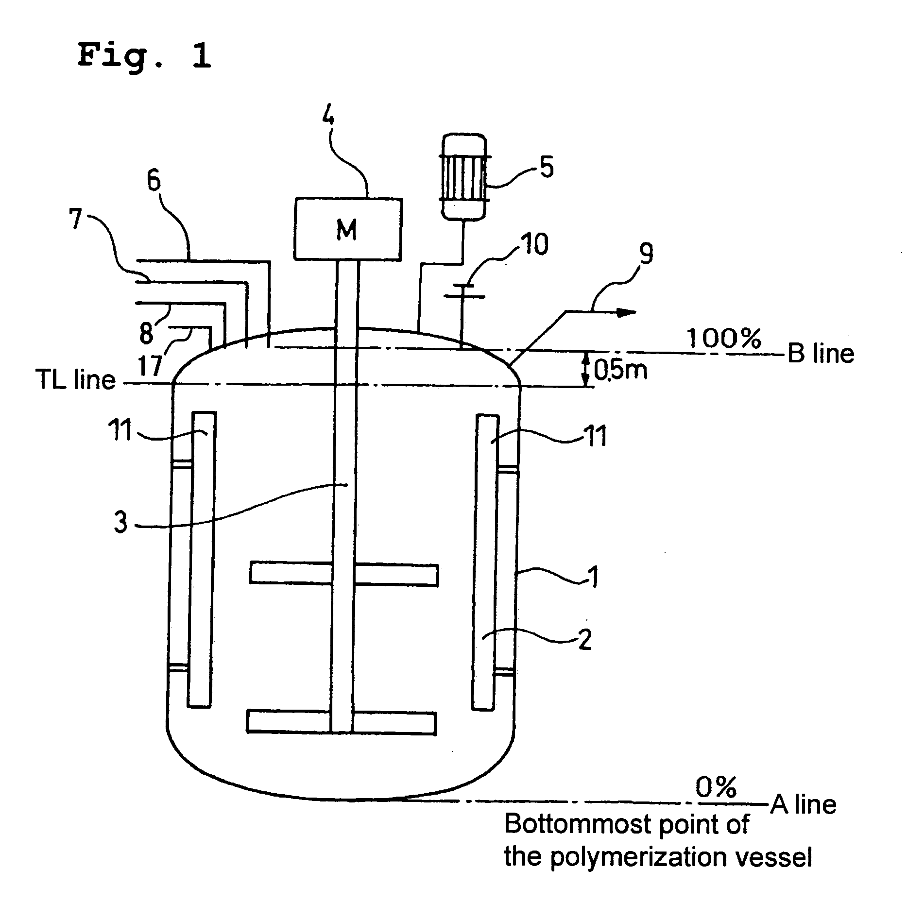
The polymerization vessel for conducting the vinyl chloride suspension polymerization was a polymerization vessel 1 with an internal capacity of 130 m3, which had been coated in advance with a scale adhesion prevention agent to form a scale adhesion prevention film on the internal surface, and was fitted with a reflux condenser 5. This polymerization vessel 1 was charged with 54,900 kg of ion exchange water, 13.8 kg of partially saponified polyvinyl alcohol, and 9.2 kg of hydroxypropylmethyl cellulose. Using an electric wave liquid level gauge 10 which radiated microwaves with a frequency of 5.8 GHz, confirmation was made that the liquid level at this point was consistent with the liquid quantity calculated in consideration of the difference in specific gravity depending on temperature. Subsequently, the inside of the polymerization vessel was evacuated with a vacuum pump until the internal pressure reached 7.98 kPa (gauge pressure), and 47,700 kg of vinyl chloride monomer was then...
example 2
With the exception of replacing the electric wave liquid level gauge with a frequency of 5.8 GHz described in the example 1 with an electric wave liquid level gauge with a frequency of 6.0 GHz, polymerization, extraction and washing were performed in the same manner as the example 1. The liquid level of the polymerization vessel contents was able to be measured during both the polymerization step and the steps outside the polymerization step.
example 3
The polymerization vessel 1 of internal capacity 130 m3 with an attached reflux condenser was used. Furthermore, an electric wave liquid level gauge which radiated microwaves with a frequency of 5.8 GHz was used as the electric wave liquid level gauge 10. A condensation product of 1-naphthol and aldehyde (a scale adhesion prevention agent) was applied to the internal surfaces of the polymerization vessel and the inside of the reflux condenser, thus forming a scale adhesion prevention film. The polymerization vessel was then charged with 54,900 kg of ion exchange water, 13.8 kg of partially saponified polyvinyl alcohol, and 9.2 kg of hydroxypropylmethyl cellulose. Using the electric wave liquid level gauge 10, confirmation was made that the liquid level at this point was consistent with the liquid quantity calculated in consideration of the difference in specific gravity depending on temperature. Subsequently, the inside of the polymerization vessel was evacuated with a vacuum pump ...
PUM
| Property | Measurement | Unit |
|---|---|---|
| Percent by mass | aaaaa | aaaaa |
| Percent by mass | aaaaa | aaaaa |
| Fraction | aaaaa | aaaaa |
Abstract
Description
Claims
Application Information
 - R&D Engineer
- R&D Manager
- IP Professional
- Industry Leading Data Capabilities
- Powerful AI technology
- Patent DNA Extraction
Browse by: Latest US Patents, China's latest patents, Technical Efficacy Thesaurus, Application Domain, Technology Topic, Popular Technical Reports.
© 2024 PatSnap. All rights reserved.Legal|Privacy policy|Modern Slavery Act Transparency Statement|Sitemap|About US| Contact US: help@patsnap.com