Fuel cell system
- Summary
- Abstract
- Description
- Claims
- Application Information
AI Technical Summary
Benefits of technology
Problems solved by technology
Method used
Image

Examples
first embodiment
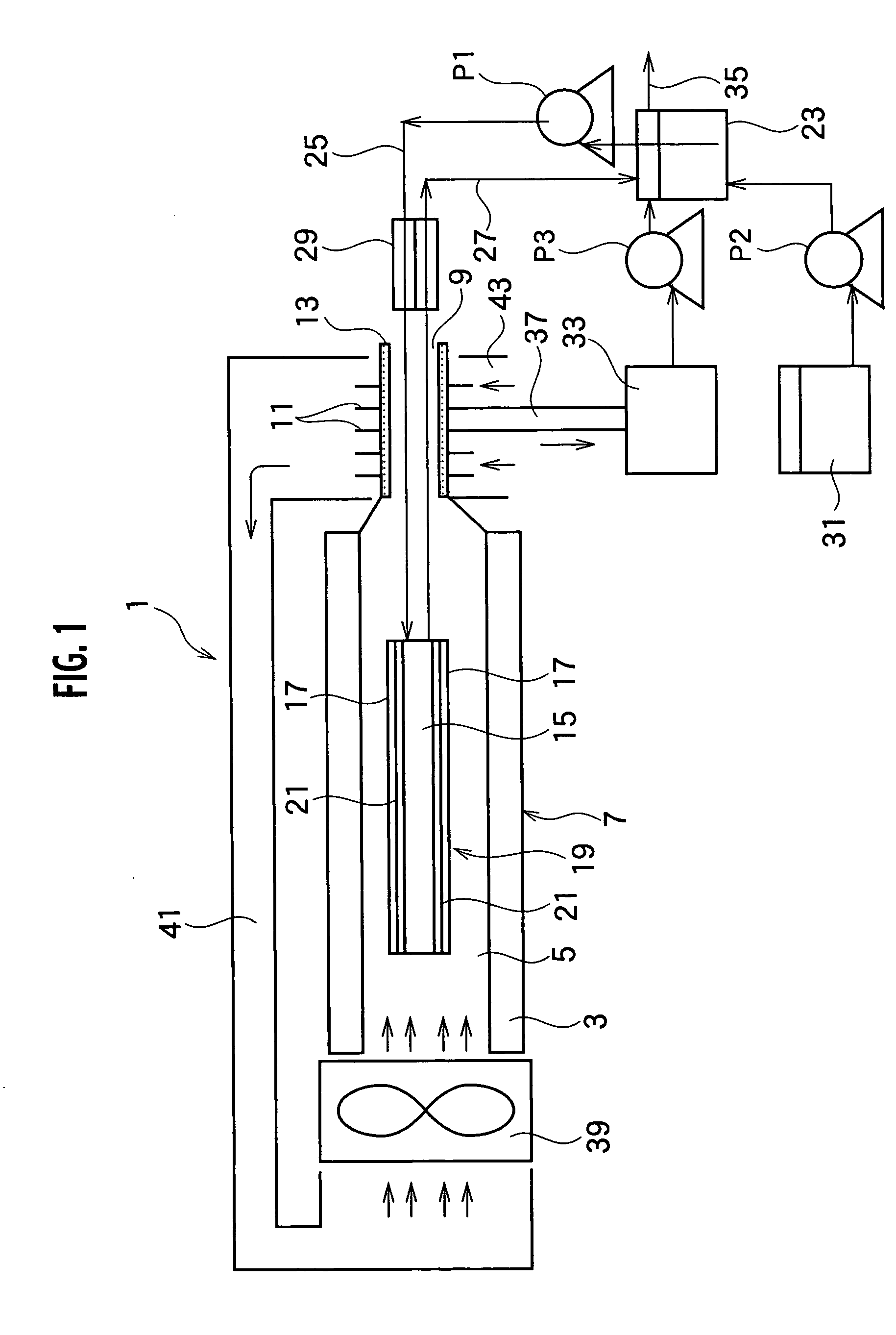
[0020] Referring to FIG. 1, a fuel cell system 1 according to the present invention is provided with a case 7 formed in a tubular shape, which encloses a space 5. Both ends of the space 5 are opened so as to permit an airflow through the space 5 for supplying air as an oxidant. A cross-section thereof preferably has a square or rectangular shape, where the rectangular shape is long sideways and the sideways direction is perpendicular to a plane of the paper of FIG. 1. The cross-sectional shape is not limited to square and rectangular but can be formed in various shapes.
[0021] The case 7 is preferably provided with a heat insulator 3 along the case 7 for heat insulation between the interior and the exterior thereof. As the heat insulator 3, various means can be employed. Preferably, heat insulating material such as glass wool, ceramics or foam plastic can be applied. Alternatively, a thin airtight chamber, an interior of which is kept in a vacuum or filled with heat insulating gas su...
second embodiment
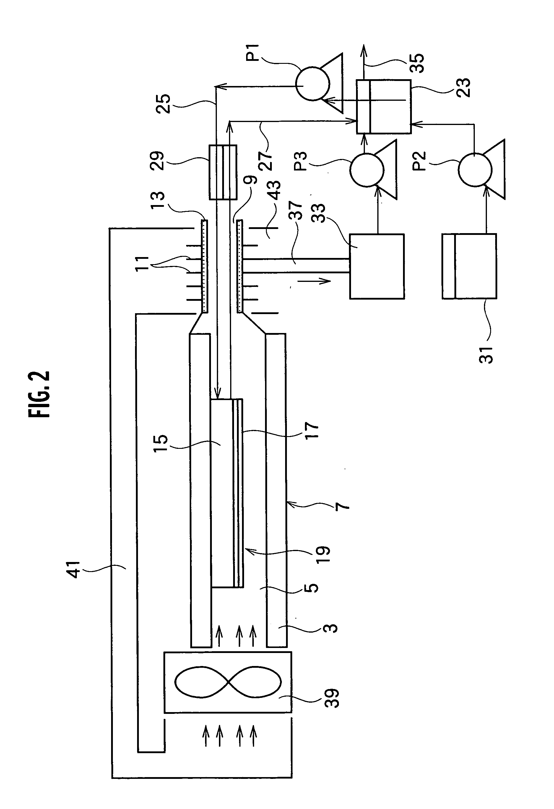
[0036] the present invention will be described hereinafter with reference to FIG. 2. In the following description, substantially the same elements as the aforementioned description are referenced with the same numerals and the detailed descriptions are omitted.
[0037] As compared with the above first embodiment, one set of the cathode 17 and the electrolyte membrane 21 is omitted and the anode 15 is supported by the inner surface of the case 7. Either direct adhesion or any support member interposed therebetween may be employed as an aspect of the support manner. As well as having the same effect as the above first embodiment, the second embodiment makes the fuel cell system as a whole further small-sized because the case 7 can be constituted in a thinner shape.
third embodiment
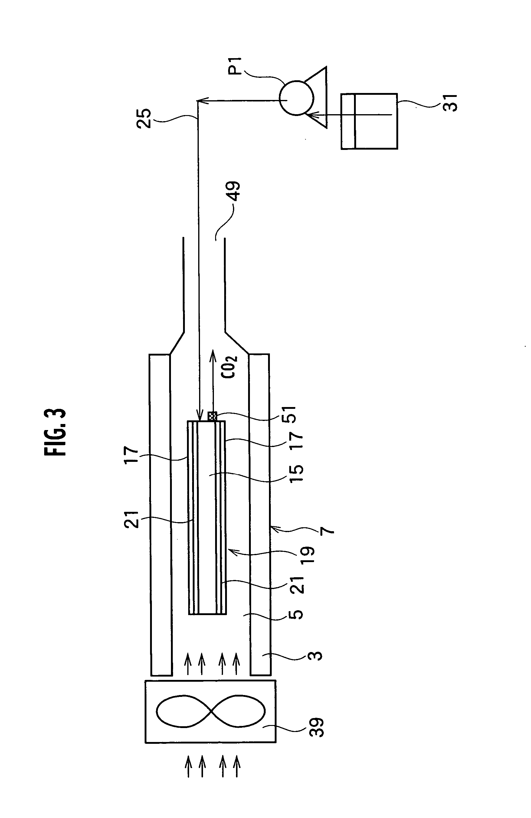
[0038] the present invention will be described hereinafter with reference to FIG. 3. In the following description, substantially the same elements as the aforementioned description are referenced with the same numerals and the detailed descriptions are omitted.
[0039] As compared with the above first embodiment, the water tank 33, the connection channel 37 connected thereto, the mixing tank 23 and the pumps P2, P3 are omitted and the fuel tank 31 is directly connected to the pump P1. Furthermore, the recovery flow path 27 and the heat exchanger 29 are omitted and CO2 generated at the anode 15 is separated at a gas-liquid separation membrane 51 provided at end peripheries of the anode 15 and exhausted through the outflow path 59. Moreover, the heat exchanging unit 11 and the air duct 41 having the opening portion 43 encircling the heat exchanging unit 11 are omitted and the air is supplied to the cathode 17 by means of the fan 39 without heat exchange.
[0040] According to the present ...
PUM
 Abstract
Description
Claims
Application Information
 - R&D
- Intellectual Property
- Life Sciences
- Materials
- Tech Scout
- Unparalleled Data Quality
- Higher Quality Content
- 60% Fewer Hallucinations
Browse by: Latest US Patents, China's latest patents, Technical Efficacy Thesaurus, Application Domain, Technology Topic, Popular Technical Reports.
© 2025 PatSnap. All rights reserved.Legal|Privacy policy|Modern Slavery Act Transparency Statement|Sitemap|About US| Contact US: help@patsnap.com