
CT electricity taking system based on maximum power point tracking

A technology of maximum power point and electrical system, which is applied to emergency protection circuit devices, collectors, electric vehicles, etc. for limiting overcurrent/overvoltage. The effect of energy storage

Pending Publication Date: 2021-12-21
QINGDAO TOPSCOMM COMM
View PDF6 Cites 0 Cited by
  • Summary
  • Abstract
  • Description
  • Claims
  • Application Information

AI Technical Summary

Problems solved by technology

In order to improve the power extraction efficiency and solve the problem of insufficient power extraction under low current, the patent "A Simulation Optimization Method for Energy Harvesting CT Based on Starting Current" (CN106227961A) proposes to select a suitable CT secondary through simulation for a specific primary side current. The number of side turns and the power-taking voltage are used to ensure the maximum power-taking power, but after the primary side current changes, the maximum power-taking power cannot be guaranteed

Method used


Image

  • CT electricity taking system based on maximum power point tracking
  • CT electricity taking system based on maximum power point tracking
  • CT electricity taking system based on maximum power point tracking

Examples


Embodiment Construction

[0035] The present invention will be further described below in conjunction with the accompanying drawings and specific embodiments.

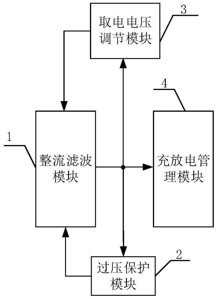
[0036] like figure 1 As shown, a CT power-taking system based on maximum power point tracking includes a rectification and filtering module (1), an overvoltage protection module (2), a power-taking voltage adjustment module (3), a charging and discharging management module (4), and a rectifying and filtering module (1). The filter module is connected to the charging and discharging management module, and is also connected to the power-taking voltage regulation module and the overvoltage protection module, and the output terminals of the power-taking voltage regulation module and the overvoltage protection module are fed back to the rectification and filtering module.

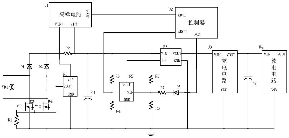
[0037]Further, the rectification and filtering module (1) includes a transient suppression diode VD1, a first rectification diode D1, a second rectification diode D2, a third rec...


PUM


Abstract

The invention relates to a CT electricity taking system based on maximum power point tracking.The system comprises a rectification and filtering module, an overvoltage protection module, an electricity taking voltage regulation module and a charging and discharging management module; electricity is taken from a high-voltage line by utilizing a CT; firstly, the rectification and filtering module rectifies and filters alternating current output by the secondary side of the CT into stable direct current; the charging and discharging management module charges a post-stage super capacitor and outputs energy stored by the super capacitor to a post-stage circuit for power supply through voltage stabilization; the overvoltage protection module prevents overvoltage of voltage output by the rectification and filtering module and discharge of excess energy; and the electricity taking voltage regulation module regulates direct-current voltage output by the rectification and filtering module in real time, and the maximum electricity taking power is ensured. The maximum CT electricity taking power can be achieved under different high-voltage line currents, it is guaranteed that equipment can work under the smaller line current, and meanwhile safe and rapid energy storage can be conducted under the large line current.

Description

technical field [0001] The invention belongs to the technical field of CT power harvesting, in particular to a CT power harvesting system based on maximum power point tracking. Background technique [0002] With the development of the national economy and the continuous increase of the scale of the power grid, the reliability of the operation of the high-voltage distribution line is facing a great test. The real-time monitoring of the status of the high-voltage line has become an important measure to ensure the reliability of the operation. Install lots of smart devices. The power supply methods of high-voltage line intelligent equipment generally include solar energy, wind energy, microwave and backup batteries, etc., but these power supply methods have problems such as limited by climate conditions, low energy conversion rate, and short service life. CT power supply can solve the above problems, and gradually It has become the first choice for the power supply mode of int...

Claims


Application Information

Patent Timeline
Patent Type & Authority Applications(China)
IPC IPC(8): H02J50/10H02H9/04H02J7/34
CPCH02J50/10H02H9/041H02J7/345
Inventor 范建华姚兴东姜文赵磊田浩
Owner QINGDAO TOPSCOMM COMM
Learn More