
Internal combustion engine exhaust cooling and removal apparatus

Inactive Publication Date: 2005-02-03
PATRY IVAN J
View PDF13 Cites 10 Cited by
  • Summary
  • Abstract
  • Description
  • Claims
  • Application Information

AI Technical Summary

Benefits of technology

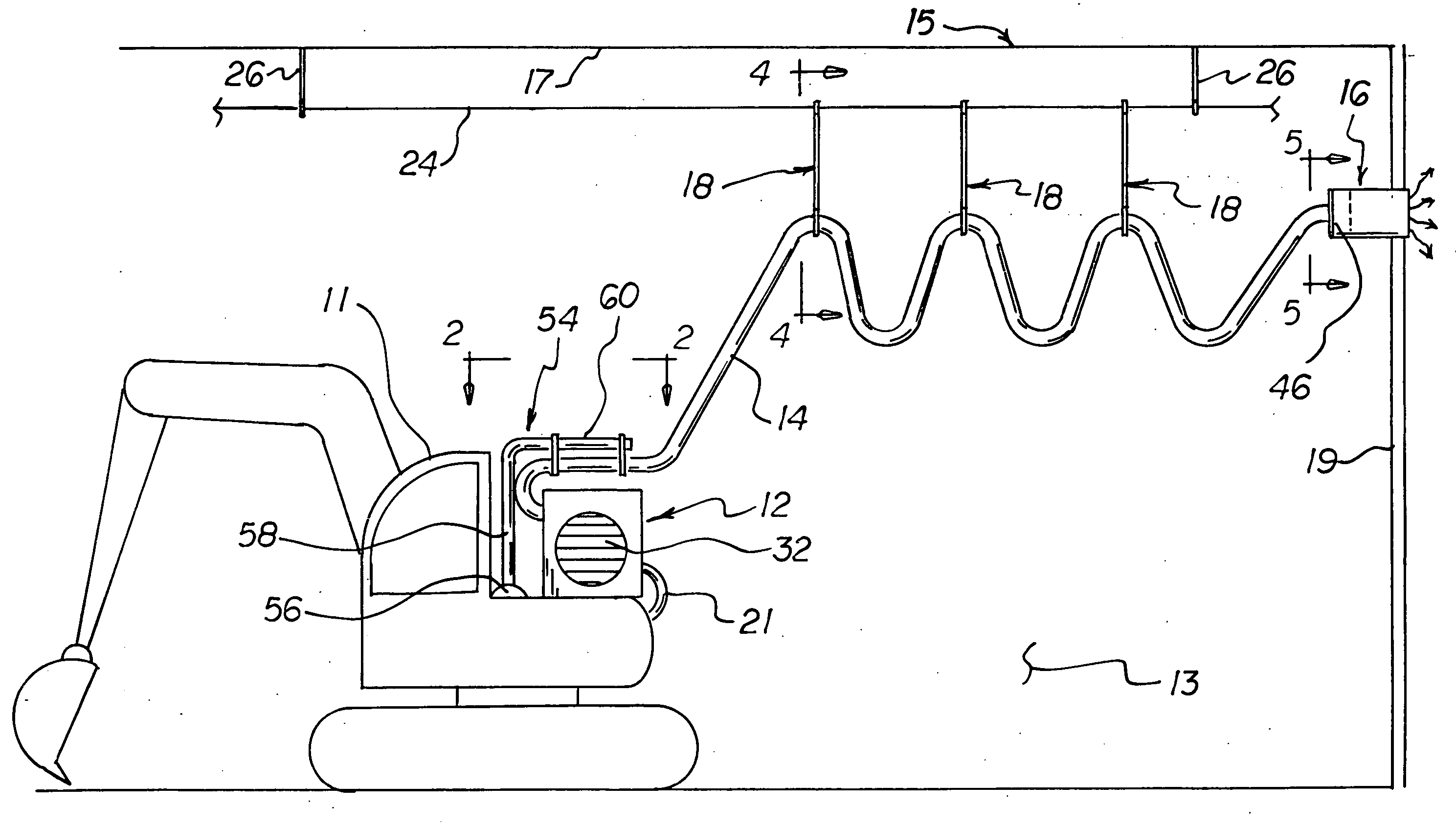
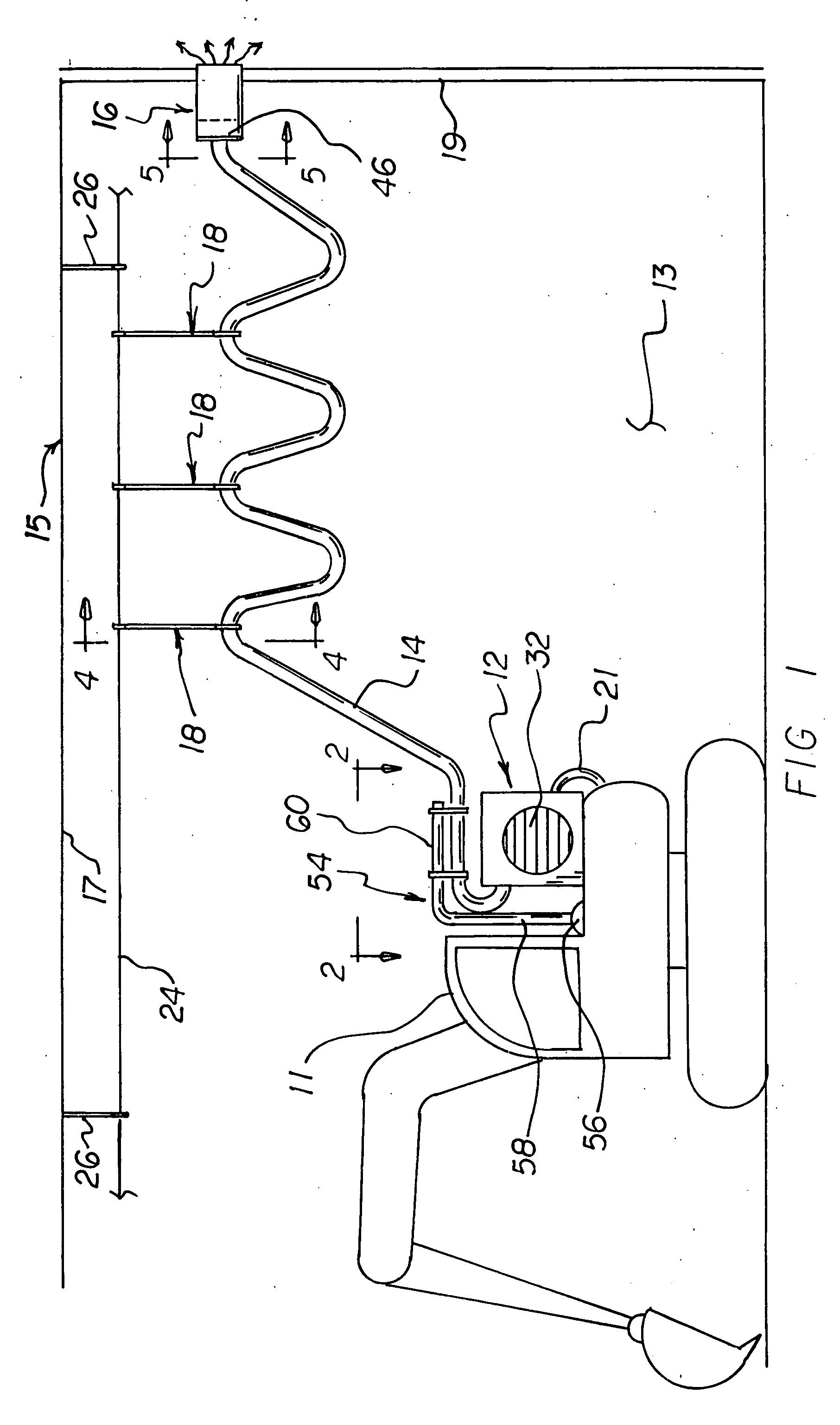
[0013] To achieve the foregoing and other advantages, the present invention, briefly described, provides an internal combustion engine exhaust cooling and removal apparatus which includes a heat exchange assembly connected to an exhaust pipe of an internal combustion engine. A flexible hose is connected to the heat exchange assembly, and an exhaust fan assembly is connected to the flexible hose. Use of the internal combustion engine exhaust cooling and removal apparatus of the invention provides a clean air environment in an indoor confined space by removing the engine exhaust gases which are hazardous to one's health. The apparatus of the invention is especially useful with non-electric powered tools and machines, such as for indoor excavations with diesel-powered excavators or other construction equipment. The apparatus of the invention can also be used with diesel-powered saws.

Problems solved by technology

It is well known that exhaust gases from an internal combustion engine are hazardous to one's health.
The hazard is greatly increased when the internal combustion engine is located in an enclosed region, such as a garage or a warehouse, where the exhaust gases can build up.
A flexible exhaust hose would generally be made from rubber-like material which is not a very good conductor of heat.
Therefore, heat exchange between the hot exhaust gases, the heated flexible exhaust hose, and the ambient air in not very efficient.
Moreover, the hot exhaust gases are often so hot that they can accelerate degradation and damage of the flexible exhaust hose.
As a result, efficient flow of exhaust gases to outside the enclosed region may be impeded.
Thus, while the foregoing body of prior art indicates it to be well known to use devices for moving exhaust gases from an internal combustion engine to outside of an enclosed space, the prior art described above does not teach or suggest an internal combustion engine exhaust cooling and removal apparatus which has the following combination of desirable features: (1) can maximize heat exchange between the hot exhaust gases and the ambient air in the enclosed region; (2) can cool the hot exhaust gases prior to entry into a flexible exhaust hose; (3) provides a heat exchanger device between the exhaust pipe of the internal combustion engine and the flexible exhaust hose; (4) provides an exhaust fan to increase the flow of the exhaust gases through the flexible exhaust hose; and (5) provides a heat exchanger device mounted on the vehicle.

Method used


Image

  • Internal combustion engine exhaust cooling and removal apparatus
  • Internal combustion engine exhaust cooling and removal apparatus
  • Internal combustion engine exhaust cooling and removal apparatus

Examples


Embodiment Construction

[0041] With reference to the drawings, a new and improved internal combustion engine exhaust cooling and removal apparatus embodying the principles and concepts of the present invention will be described.

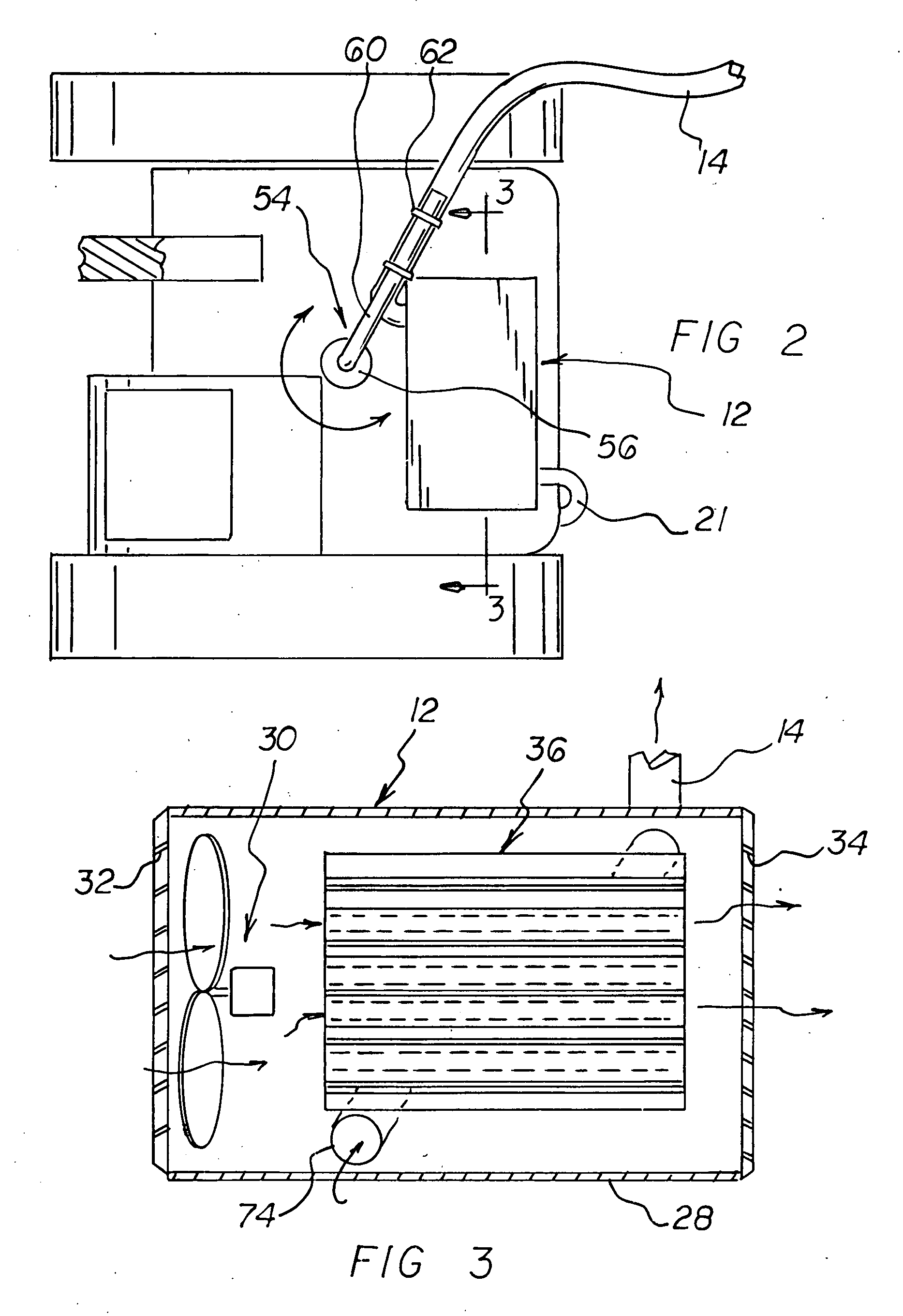
[0042] Turning to FIGS. 1-7, there is shown a preferred embodiment of the internal combustion engine exhaust cooling and removal apparatus of the invention which includes a heat exchange assembly 12 connected to an exhaust pipe 21 of an internal combustion engine. A flexible hose 14 is connected to the heat exchange assembly 12, and an exhaust fan assembly 16 is connected to the flexible hose 14. Use of the internal combustion engine exhaust cooling and removal apparatus of the invention provides a clean air environment in an indoor confined space by removing the engine exhaust gases which are hazardous to one's health. The apparatus of the invention is especially useful with non-electric powered tools and machines, such as for indoor excavations with diesel-powered excavators or o...


PUM


Abstract

An internal combustion engine exhaust cooling and removal apparatus includes a heat exchange assembly connected to an exhaust pipe of an internal combustion engine. A flexible hose is connected to the heat exchange assembly, and an exhaust fan assembly is connected to the flexible hose. Use of the internal combustion engine exhaust cooling and removal apparatus of the invention provides a clean air environment in an indoor confined space by removing the engine exhaust gases which are hazardous to one's health. The apparatus of the invention is especially useful with non-electric powered tools and machines, such as for indoor excavations with diesel-powered excavators or other construction equipment. The apparatus of the invention can also be used with diesel-powered saws.

Description

CROSS-REFERENCE TO RELATED APPLICATION [0001] This application claims priority based upon my copending Provisional Application Ser. No. 60 / 491,061, filed Jul. 31, 2003.BACKGROUND OF THE INVENTION [0002] 1. Field of the Invention [0003] The present invention relates generally to devices for carrying away exhaust gases from an internal combustion engine and, more particularly, to carrying exhaust gases to a location outside of an enclosure, such as warehouse, where the internal combustion engine is located. [0004] 2. Description of the Prior Art [0005] It is well known that exhaust gases from an internal combustion engine are hazardous to one's health. The hazard is greatly increased when the internal combustion engine is located in an enclosed region, such as a garage or a warehouse, where the exhaust gases can build up. In general, it is well known to vent the exhaust gases to a location outside the enclosed region. In this respect, throughout the years, a number of innovations have...

Claims


Application Information

Patent Timeline
IPC IPC(8): B08B15/00F01N3/02F01N13/18
CPCB08B15/002F01N3/02Y02T10/20F01N2240/02F01N2290/06F01N13/1816Y02T10/12
Inventor PATRY, IVAN J.
Owner PATRY IVAN J
Learn More