
Wind abatement system

Active Publication Date: 2011-06-21
BENNETT WAYNE E +1
View PDF9 Cites 9 Cited by
  • Summary
  • Abstract
  • Description
  • Claims
  • Application Information

AI Technical Summary

Benefits of technology

[0020]It is another object of the present invention to provide a new and improved wind abatement system which may be easily and efficiently manufactured and marketed.
[0021]It is further object of the present invention to provide a new and improved wind abatement system which is of durable and reliable constructions.
[0022]An even further object of the present invention is to provide a new and improved wind abatement system which is susceptible of a low cost of manufacture with regard to both materials and labor, and which accordingly is then susceptible of low prices of sale to the consuming public, thereby making such wind abatement system economically available to the buying public.
[0023]Even still another object of the present invention is to provide a wind abatement system for making structures, including homes, lanais, entrances, windows, garages and the like secure from high winds and hurricanes in a safe, convenient and economical manner.
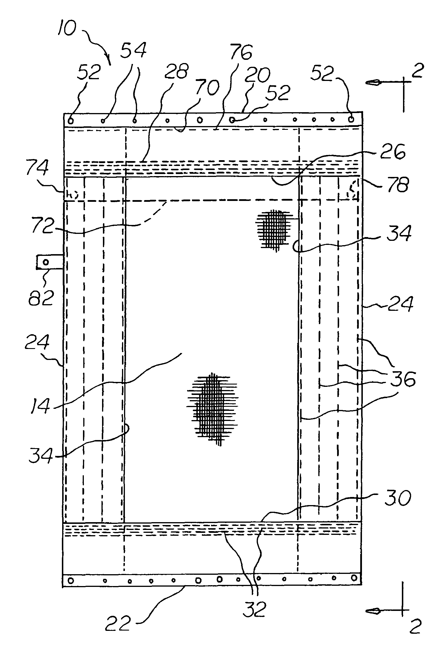
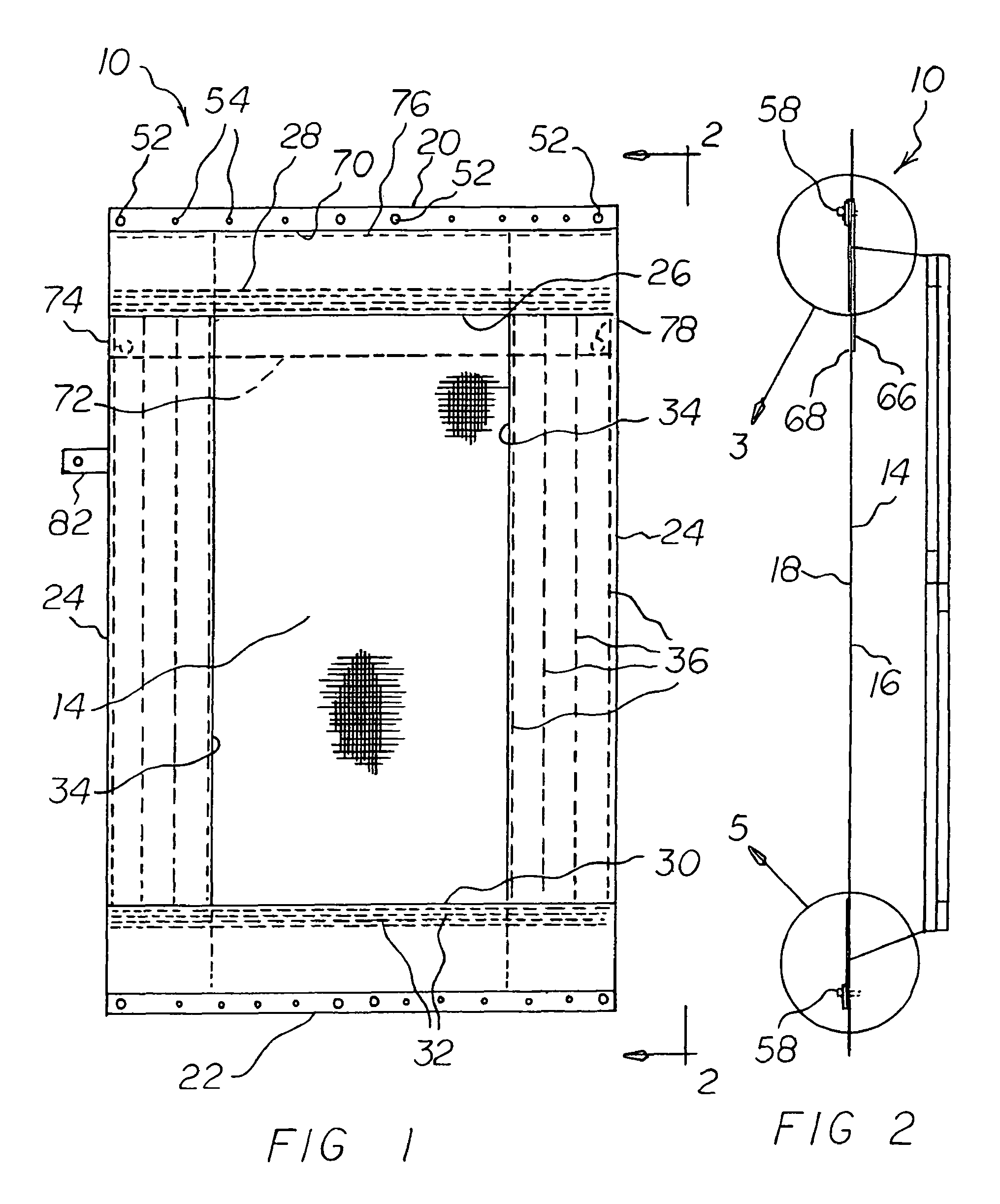
[0024]Lastly, it is an object of the present invention to provide a new and improved wind abatement system. A fabric panel has an interior and exterior face with a top, a bottom, and sides. An upper seam forms an upper passageway. A lower seam forms a lower passageway. A bar is secured within each hem. A plurality of support holes extends through the hem and bar at the top and at the bottom of the primary panel. A plurality of threaded bolts are provided. Each bolt has a threaded end. The threaded end is adapted to be received by recipient surfaces adjacent to the top and bottom of the panel. Each bolt has an exposed end. In this manner coupling and uncoupling is facilitated. Each bolt has a central portion. The central portion extends through a hole in a hem and bar at the top and at the bottom of the panel.

Problems solved by technology

While this devices fulfills its objectives and requirements, the aforementioned patent does not describe a wind abatement system that allows for making structures, including homes, lanais, entrances, windows, garages and the like secure from high winds and hurricanes in a safe, convenient and economical manner.

Method used


Image

  • Wind abatement system
  • Wind abatement system
  • Wind abatement system

Examples


embodiment 100

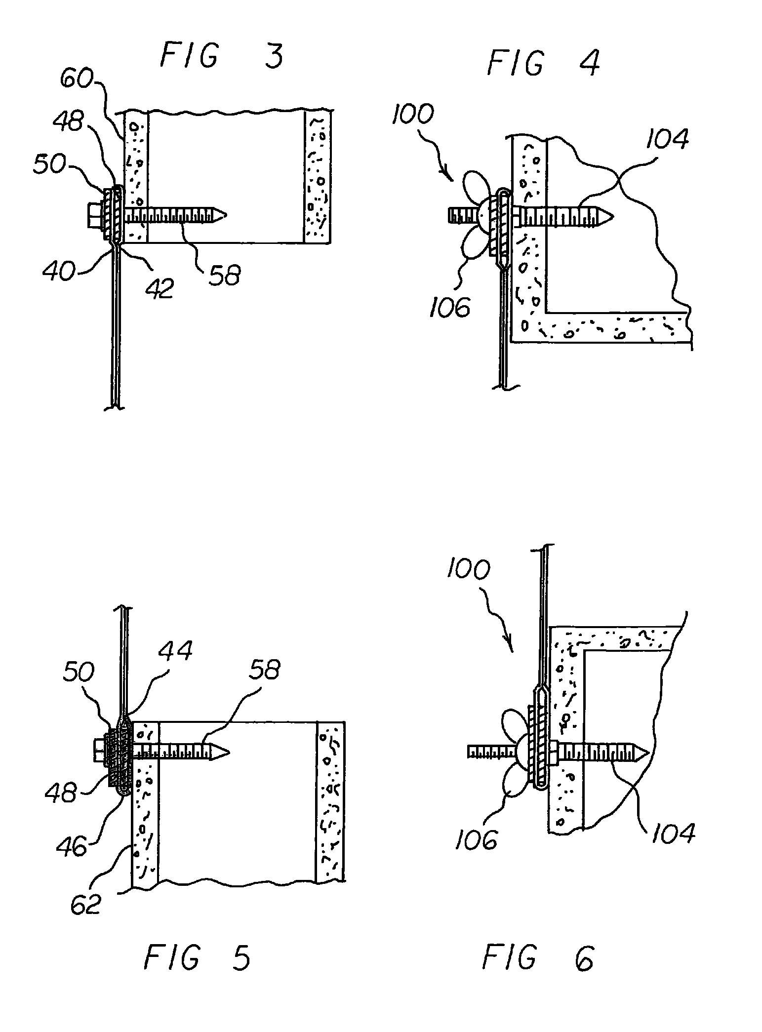
[0045]Reference is now made to the alternate embodiment 100 of FIGS. 4 and 6. The bolts each have threads 104. The threads are provided at the exposed ends. The bolts have washered wing nuts 106. In this manner the panel is adapted to be uncoupled from a recipient surface without removal of the bolts.

[0046]Reference is now made to the alternate embodiment 200 of FIG. 7. The bolts each have a head 204. The head is provided at the exposed end. A first L-shaped component 206 is provided. The first L-shaped component has an interior end 208. A first bolt 210 is provided. The first L-shaped component is supported by the first bolt 210. The first L-shaped component has an exterior end 212. A second L-shaped component 214 is provided. The second L-shaped component has an interior end 216. A second bolt 218 is provided. The second bolt is coupled to the exterior end of the first L-shaped component. The second L-shaped component has an exterior end 220. A third bolt 222 is provided. The thir...

embodiment 300

[0047]Reference is now made to the alternate embodiment 300 of FIG. 8. The bolts each have a head 304. The head is provided at the exposed end. An L-shaped component 306 is provided. The L-shaped component has an interior end 308. The interior end is supported by a bolt. The L-shaped component has an exterior end 310. A supplemental bolt 312 is provided. The supplemental bolt couples the exterior end to a panel.

[0048]Note is taken that the bolts extending into the recipient surfaces of FIGS. 7 and 8 require anchors for maximum strength. Note is also taken that the enlarged cross sectional view of FIGS. 3 through 8 do not show the secondary panel. This is to more clearly illustrate the relationship between the primary panel and the bars with regard to the bolts and recipient surfaces.

[0049]As to the manner of usage and operation of the present invention, the same should be apparent from the above description. Accordingly, no further discussion relating to the manner of usage and oper...


PUM


Abstract

A fabric panel has an interior and exterior face with a top, a bottom, and sides. An upper seam forms an upper passageway. A lower seam forms a lower passageway. A bar is secured within each hem. A plurality of support holes extends through the hem and bar at the top and at the bottom of the primary panel. A plurality of threaded bolts are provided. Each bolt has a threaded end. The threaded end is adapted to be received by recipient surfaces adjacent to the top and bottom of the panel. Each bolt has an exposed end. In this manner coupling and uncoupling is facilitated. Each bolt has a central portion. The central portion extends through a hole in a hem and bar at the top and at the bottom of the panel.

Description

BACKGROUND OF THE INVENTION[0001]1. Field of the Invention[0002]The present invention relates to a wind abatement system and more particularly pertains to making structures, including homes, lanais, entrances, windows, garages and the like secure from high winds and hurricanes in a safe, convenient and economical manner.[0003]2. Description of the Prior Art[0004]The use of wind protection systems of known designs and configurations is known in the prior art. More specifically, wind protection systems of known designs and configurations previously devised and utilized for the purpose of protecting structures from wind through known methods and apparatuses are known to consist basically of familiar, expected, and obvious structural configurations, notwithstanding the myriad of designs encompassed by the crowded prior art which has been developed for the fulfillment of countless objectives and requirements.[0005]By way of example, U.S. Pat. No. 6,176,050 issued Jan. 23, 2001 to Gower r...

Claims


Application Information

Patent Timeline
IPC IPC(8): E06B3/30
CPCE06B2009/005E06B9/00
Inventor BENNETT, WAYNE E.BENNETT, ROSALIE
Owner BENNETT WAYNE E
Learn More