
Method and apparatus for multi-realm system modeling

a multi-realm system and modeling technology, applied in the field of modeling systems, can solve the problems of complex models of complex systems that are often too complex to be effectively processed as a monolithic whole, difficult to achieve integration of processing results, and difficulty further compounded

Active Publication Date: 2005-01-27
VMWARE INC
View PDF3 Cites 129 Cited by
  • Summary
  • Abstract
  • Description
  • Claims
  • Application Information

AI Technical Summary

Benefits of technology

The invention provides a method for modeling a dynamic or static system using realms to represent components and relationships between them. The system is divided based on criteria into components and relationships modeled by objects in the realms. The realms can have associations with each other, which unifies them and identifies them as representing the same system component or components. The model can be used in various applications such as enterprise management systems, business service management systems, real-time enterprise systems, IT systems, utility systems, and more. The technical effect of the invention is to provide a flexible and effective way to model complex systems.

Problems solved by technology

For example, the model of a processor may include specifying typical processor operations, or even typical processor problems, and the events each problem can cause.
Complex models of complex systems are often too intricate to be effectively processed as a monolithic whole.
If systems are divided into subsystems, known modeling methods fail to provide suitable techniques for dividing the system in a manner that enables processing to be performed on subsystems, and then results integrated into a system-wide result.
Such integration of processing results is difficult to achieve.
This difficulty is further compounded when the system is dynamic, i.e., components / relationships are added / deleted / modified in real-time.
Monolithic modeling, however, has many problems that increase the complexity of both representing the system and performing processing on it.
Firstly, the potentially large number of components may render the approach impractical.
It may be difficult to employ any manual or automated method to create a monolithic model of such a large number of components and their relationships.
This problem is compounded by the typical dynamic nature of IT systems having frequent adds / moves / changes.
Thirdly, it may be impractical to perform any processing on the overall system because of the number of components involved.
Several difficulties arise in processing subsystem models in a manner that enables integrating the results.
Many of these difficulties stem from dependencies and relationships between the behaviors of objects that are assigned to different subsystem models.
It is difficult to separate the monolithic model into subsystems also because, e.g., several types of processing require understanding the overall system model.
For example, fault management processing (the isolation of faults within a system) may require correlating events across many subsystem models because problems in one component often spread symptoms to related components in other subsystems, e.g., a problem in a network device may ultimately cause application transactions to time out.
Due to the overall system complexity, it is very difficult to understand what is happening in the system as a whole without understanding the relationships between the different subsystems.
As another example, referring to the example in FIG. 1, a degraded response time perceived by the client database query may be due to an ineffective load balancing director, which may be due to a malfunction of a database server in the cluster, which in turn may be due to a non-responsive interface event, which in turn may be due to a failed network connection event, which in turn may be due to broken VPN link connectivity as a result of a hardware problem at the service provider.
The hardware problem is the root cause for all the events across multiple subsystems, including the database access failure event.
The difficulty is that this analysis requires correlation processing of events across subsystem boundaries.
No single subsystem in this example has enough data to identify the root cause.
It is also difficult to unify different levels of abstractions or different perspectives on the same components or their behavior.
In other words, there can be difficulty in expressing behaviors in terms of components and relationships familiar to the subsystem, while hiding details of other subsystems.
There can also be difficulty in capturing the meaning of a relationship between components in different subsystems.
If a database server has problems, the transaction may or may not suffer.
If the problem impacts performance, it will affect only transactions that have real-time response constraints.
Only if the client-server relationship in the example is real-time, should the modeled server failure cause a performance impact on the client subsystem.

Method used


Image

  • Method and apparatus for multi-realm system modeling
  • Method and apparatus for multi-realm system modeling
  • Method and apparatus for multi-realm system modeling

Examples


example 1

Database Service Model

[0145] A modeling method in accordance with one or more embodiments of the invention can be applied to the database service example shown in FIG. 1. One possible division of the system is generally depicted in FIGS. 11 and 12, which include the objects of FIG. 1 with the addition of relationship objects. Various other divisions are also possible depending on the particular division criteria selected.

[0146]FIG. 12 displays a possible definition of realms for the database service. In FIG. 12, a client realm (Realm 1) includes the client application and the client connection to the service. An application realm (Realm 2) includes the client application, the web server, the load balancer, and the database application. An OS realm (Realm 3) includes the scheduler, the processes, and the resource (memory and processor) allocations at each server. An infrastructure realm includes the VPN link and devices to support the VPN service between the client and the service ...

example 2

Generic End-to-End Infrastructure Management

[0160] One of the long-standing difficulties in the enterprise management space is managing the infrastructure end-to-end to optimize performance and availability of IT-dependent business services. The challenge is that the technology domains (applications, security, databases, servers, storage, network equipment, network protocols, etc.) are tightly intertwined, and thus behaviors propagate across these domains. Managing infrastructure end-to-end requires understanding the individual objects, the individual realms, behaviors, and how they propagate across related objects and related realms. An example of the use of MRSM in accordance with one or more embodiments of the invention for managing end-to-end infrastructures is as follows:

[0161] The infrastructure can be modeled and divided into the following realms: (1) physical network objects and their relationships; (2) data link layer objects and their relationships; (3) network layer obj...

example 3

Applications and Business Services Management Model

[0168] Another long-standing challenge in the enterprise management space is managing the infrastructure to optimize business performance. Business performance can be tightly dependent on the underlying end-to-end IT infrastructure, which can include applications, databases, servers, storage, network equipment, etc. To drive the management of IT by business objectives requires understanding the complex web of relationships within and across subsystems, and understanding how behaviors propagate, not only within the infrastructure, but also across applications, services, and users. FIG. 20 depicts a generic enterprise management system. The triangle shape depicts different layers or division of the overall system into business processes, applications that support business processes, and the IT infrastructure that, in turn, supports the applications. Furthermore, business services are intimately dependent on their supporting technolog...


PUM


Abstract

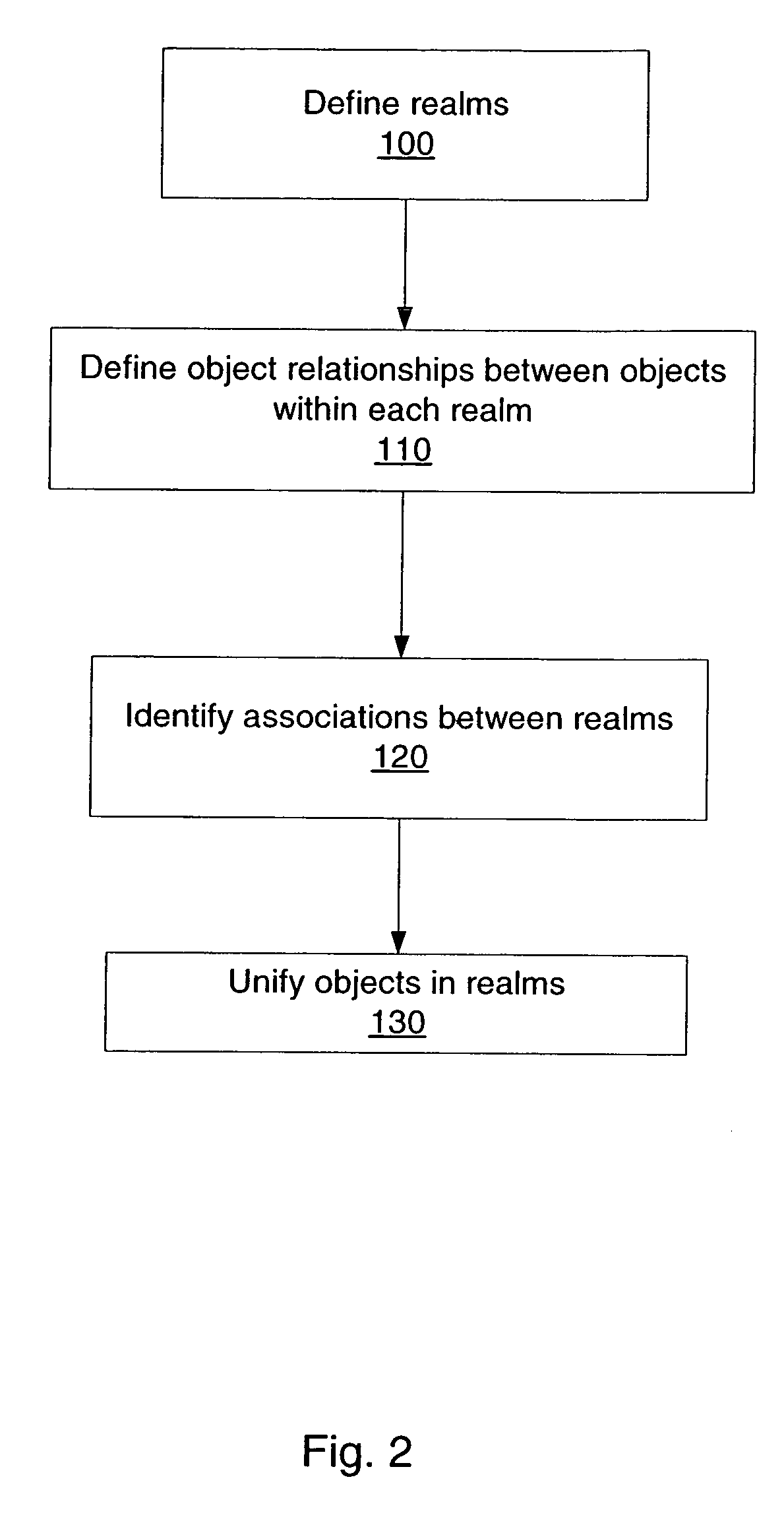
A method and apparatus are provided for multi-realm system modeling (MRSM) for dividing systems into components, defining realms containing objects representing system components, optionally defining relationships between the system components, defining associations between realms sufficient to unify objects in the realms when needed, and unifying objects in the realms based on the associations. The realms are defined in a way that enables unified processing for various applications of MRSM.

Description

RELATED APPLICATION [0001] The present invention is based on and claims priority from U.S. Provisional Patent Application Ser. No. 60 / 459,007 filed on Mar. 31, 2003 and entitled SYSTEM MANAGEMENT USING MULTI-REALM SYSTEM MODELING, which is incorporated by reference herein in its entirety.BACKGROUND OF THE INVENTION [0002] 1. Field of the Invention [0003] The present invention generally relates to modeling systems in order to perform processing functions such as, e.g., modeling, analysis, control, design, simulation, and management. More particularly, it relates to modeling dynamic or static systems by integrating models of intersecting or non-intersecting pieces of the system. Pieces of the system can be defined in a way that enables processing to be performed on individual models of each piece, and the results to be integrated into a system-wide result. [0004] 2. Description of Related Art [0005] The present application relates to modeling dynamic or static systems, which can inclu...

Claims


Application Information

Patent Timeline
Patent Type & Authority Applications(United States)
IPC IPC(8): G06FG06F15/173G06F17/50G06F19/00G06Q10/04
CPCG06Q10/04
Inventor YEMINI, SHAULA ALEXANDERDESIMONE, SALVATOREFLORISSI, PATRICIA GOMES SOARESKLIGER, SHMUELYARDENI, EYAL
Owner VMWARE INC
Learn More